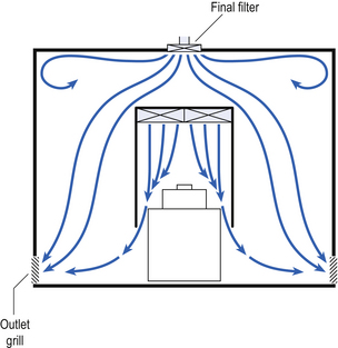
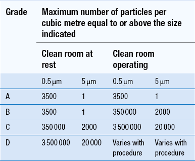
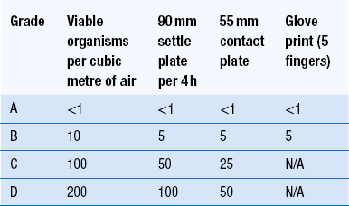
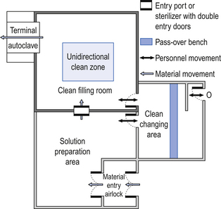
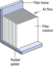
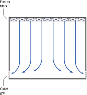
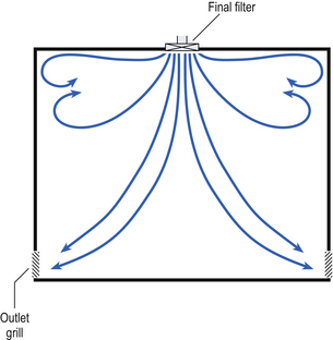
40 The production of sterile medicinal products has special requirements. These products must be produced in conditions that ensure that they are pure. They must also be free from viable organisms and pyrogens with limited, or ideally no, particulate contamination. It is thus important that only carefully regulated and tested procedures are used to manufacture sterile products. Clean areas for the production of sterile products are classified into grades A, B, C and D. These grades are categorized by the particulate quality of the environmental air when the clean area is operating in both a ‘manned’ and ‘unmanned’ state. In addition, these areas are graded by the microbial monitoring of the environmental air, surfaces and operators when the area is functioning. The standards are shown in Tables 40.1 and 40.2. There are two common procedures used to manufacture sterile products. The first method involves the preparation of products that will be terminally sterilized. The second method involves the aseptic filling of containers that are not exposed to terminal sterilization. Aseptic filling requires a higher environmental quality for the preparation of solutions and the filling of containers. The qualities of the clean rooms used for these production procedures are detailed in Tables 40.3 and 40.4. Table 40.3 Conditions for preparing terminally sterilized products Table 40.4 Conditions for the production of aseptically prepared products The sterile production unit must be separated from the general manufacturing area within the hospital pharmacy or factory. This sterile production unit must not be accessible to unauthorized personnel. The filling room is typically serviced from an adjacent preparation room. This allows supporting personnel to assemble and prepare materials. Staff within the filling room area then use these materials. Figure 40.1 shows the layout of rooms for the production of terminally sterilized medicines such as small or large volume injections. Potential sources of particles and microbial contaminants occurring within the clean room are: Each of these possible sources can be minimized as described below. The HEPA filters use pleated fibreglass paper as the filter medium. Parallel pleats of this filter material increase the surface area of the filter and increase the airflow through the filter. This structure allows the filter to retain a compact volume. Aluminium foil is used to form spacers in the traditional type of HEPA filter. Spacers are not used in the more modern ‘mini-pleat’ type of filter design. These mini-pleat filters are now widely used. They have a shallower depth in construction than the traditional HEPA filter. Within the structure of the filter, the filter material is sealed to an aluminium frame (Fig. 40.2). At least one side of the filter is protected with a coated mild steel mesh. HEPA filters exhibit: The filter material possesses a uniform resistance and is constructed with a large number of parallel pleats. This results in the air downstream of the filter face flowing uniformly with a unidirectional configuration. The number of air changes in clean rooms is affected by: Air enters the room through a complete wall or ceiling of high-efficiency filters. This air will sweep contamination in a single direction to the exhaust system on the opposing wall or floor (Fig. 40.3). In the interests of economy, the exhaust grill may be fitted low down on the wall. The velocity of the air is about 0.3 m/s in downflow air from ceiling filters and 0.45 m/s in crossflow air. These are highly efficient airflow systems. However, one major disadvantage of these rooms for pharmaceutical use is that they are expensive to construct. They also use much more conditioned air than rooms with non-unidirectional airflow. This greatly increases their operating costs. Owing to these factors, unidirectional airflow clean rooms are seldom used for pharmaceutical purposes. Air enters the clean rooms through filters and diffusers that are usually located in the ceiling. It exits through outlet ducts positioned low down on the wall or in the floor at sites remote from the air inlet (Fig. 40.4). With the use of this system, the filtered inlet air mixes with and dilutes the contaminated air within the room. As the clean room air has been previously heated and cleaned, it can be recirculated to save energy, a little fresh air being introduced with each air change cycle. Various designs of diffuser are used with this ventilation system. These affect the air movement and the cleanliness of the rooms. The perforated plate diffuser produces a jet flow of air directly beneath it. This jet of air will carry contamination at its edges. However, it does produce high-quality air directly under the diffuser. It is thus important that production procedures are located directly below the diffuser. By contrast, the air released from the bladed diffuser will mix with the clean room air. This diffuser thus produces a reasonably constant quality of air throughout the room. The combination airflow system is often selected for pharmaceutical clean room applications as it: Several types of unidirectional flow workstations or benches are used in this combination-type room. Various vertical unidirectional airflow systems are used in combination clean rooms. With one system, the critical area is surrounded by a plastic curtain with vertical unidirectional downflow air ‘washing’ over the manufacturing process and exiting under the plastic curtains into the general clean room area (Fig. 40.5). An alternative system is often used with the small-scale combination-type clean room in hospital pharmacies. With this system, a horizontal airflow cabinet (Fig. 40.6) is used as the workstation. With these cabinets, a fan forces air through a HEPA filter located at the rear wall of the workstation. The air that exits from the filter first washes over the critical work area before washing over the arms and upper body areas of the operator. Contamination arising from the operator is thus kept downstream of the critical procedures. Grade A environmental conditions are achieved at the critical work area. A similar workstation known as a vertical laminar airflow cabinet (Fig. 40.7) could also be used in the combination room. This cabinet passes air vertically downwards from the ceiling of the cabinet over the critical working area. It produces a Grade A environmental quality. The air exits from the front of the workstation. Figure 40.5 Airflow patterns in a mixed-flow clean room with non-unidirectional airflow background environment and unidirectional airflow protection for a critical area.
Production of sterile products
Introduction
Sterile product production
Procedure
Required standard before terminal sterilization
Preparation of solutions for filtration and sterilization
Grade C is used for products which support microbial growth
Grade D acceptable if solutions subsequently filtered
Filling small and large volume parenterals
Grade C. For products with a high risk of contamination such as wide-necked containers, a Grade A laminar airflow workstation with Grade C background
Preparation and filling of ointments, creams, suspensions and emulsions
Grade C
Procedure
Required standard
Handling of sterile starting materials
Grade A with Grade B background or Grade C if solution filtered later in production process
Preparation of production solutions
Grade A with Grade B background or Grade C if sterile during filtered production
Filling of aseptically prepared products such as small and large volume parenterals
Grade A with Grade B background
Preparation and filling of ointments, creams, suspensions and emulsions
Grade A with Grade B background
Premises
Environmental control
Air supply
Unidirectional airflow systems
Non-unidirectional airflow systems
Combination systems
![]()
Stay updated, free articles. Join our Telegram channel

Full access? Get Clinical Tree


Production of sterile products


Only gold members can continue reading. Log In or Register to continue
