Figure 10.1Capsules produced from two encapsulation methods: (a) manual filling (loose powder); (b) automatic machine (plug).
Machines having five tamping stations (Bosch GKF and Höfliger-Karg machines) compress the powder once at each station while those containing three tamping stations (Harro-Höfliger KFM machines) compress the powder twice at each station. After tamping, the dosing disc moves to the ejection station and a piston ejects the powder plug into an empty capsule body.22,23
Dosator-based machines, which are represented by the Zanasi and MG2, use a dosator for dosing powders. A dosator is a hollow cylinder containing a spring-controlled moving piston. Filling occurs when a dosator is immersed into a uniform powder bed, and a plug is then formed when the powder is densified by the piston. Plugs are then ejected into capsule bodies.
Modeling/Powder Fill Estimation during Encapsulation
It is important to predict the amount of powder that can be filled into a capsule or the maximum fill a certain capsule size can hold. This information will affect capsule size selection, number of capsules to be administered per dose, and the processing method to be pursued.
Estimations in Manual Capsule Filling
Traditionally, encapsulation fill weight is estimated according to Equation 10.1:
 10.1
10.1where W is the fill weight, V is the capsule body volume, and ρ is the powder density.
Capsule volumes and dimensions are provided by capsule vendors for different capsule sizes24 and are discussed in more detail in Chapter 2. The density term in Equation 10.1 could be either the bulk or the tapped density, but the tapped density is often used since the maximum fill weight of a capsule is usually targeted. Equation 10.1 is helpful in predicting fill weights of manually filled capsules and, to some extent, capsules filled by tamping (i.e., dosing disc).
Predictions do not necessarily correlate to dosator-based filling machines, because powders pack differently in dosators compared to capsule bodies. Therefore, a separate equation is required to make predictions in dosator-based machines. Failure of Equation 10.1 in making accurate predictions in dosator-based machines is further depicted in the case study below.
The Need for a Dosator-Based Model—A Case Study
BI 671800 ED is an investigational new pulmonary drug developed as a 100-mg capsule dosage form (200 mg fill weight) that was hand-filled into size 1 capsules. A 200-mg strength (400 mg fill weight) of the same common blend was to be developed using a capsule no larger than size “0EL.” Both strengths were needed for Phase II clinical studies and were to be manufactured by a dosator-based encapsulation machine. The key challenge for the higher-strength development was that the fill weight was to be doubled without doubling the capsule volume (capsule body volume = 0.50 mL and 0.78 mL for size 1 and 0EL capsules, respectively).
The bulk and tapped powder densities of the BI 671800 ED powder blend (0.37 and 0.61 g/mL, respectively) were used according to Equation 10.1 to estimate fill weights in different sized capsules. According to these estimates (Table 10.1), encapsulating 400 mg of the powder blend (200 mg strength) in a size 0EL capsule was feasible since up to 476 mg of powder can be filled in a size 0EL capsule.
Capsule Size | Capsule Body Volume (mL)a | Predicted Fill Weight (mg) Based On | |
|---|---|---|---|
ρ(Bulk) | ρ(Tap) | ||
00EL | 1.02 | 377 | 622 |
00 | 0.91 | 337 | 555 |
0EL | 0.78 | 289 | 476 |
0 | 0.68 | 252 | 415 |
1 EL | 0.54 | 200 | 329 |
1 | 0.50 | 185 | 305 |
2 EL | 0.41 | 152 | 250 |
2 | 0.37 | 137 | 226 |
3 | 0.30 | 111 | 183 |
4 | 0.21 | 78 | 128 |
5 | 0.13 | 48 | 79 |
a Based on Capsugel Coni-Snap capsules.
Hand-filling experiments confirmed the estimates and demonstrated that 400 mg of the BI 671800 ED powder blend could be hand-filled into a size 0EL capsule after tapping. Encapsulation attempts using a dosator-based automatic filling machine (Zanasi 6F) were successful for the 100-mg strength (200 mg fill weight) in size 1 capsules, but not the 200-mg strength (400 mg fill weight), which could not be encapsulated in a capsule smaller than size “00.” The maximum fill weight that could be encapsulated in a size 0EL capsule using the Zanasi 6F was 380 mg, which is significantly different from the 476-mg fill weight predicted by Equation 10.1 (Table 10.1). This shows that Equation 10.1 is not an accurate predictor of fill weight in dosator-based machines and that a separate equation or model is needed for such machines.
Estimations in Dosator-Based Capsule Machines
Many dosator-based machines have the same dosing principle but differ in some of the operational details. This section will describe dosator machines based on a Zanasi-type machine; differences between the Zanasi and other encapsulation machines are further described in the “Machine Differences” section.
A dosator is a hollow cylinder (i.e., dosing tube) containing a spring-controlled moving piston (Figure 10.2). In dosator-based machines, dosing occurs through three sequential stages: First, the powder bowl is filled and uniformly leveled to form a powder bed; then, the target dose is filled into the dosator and densified into a plug. Finally, the plug is ejected from the dosator into the capsule body; these steps are discussed in more detail in Chapter 6. Powder densification within a dosator is necessary to achieve a powder arch strong enough to support the powder’s weight and keep it in the dosator during transfer between dosing and ejection stations. Unlike dosing discs that involve multiple steps, filling and densification in dosator-based machines occur in a single step.
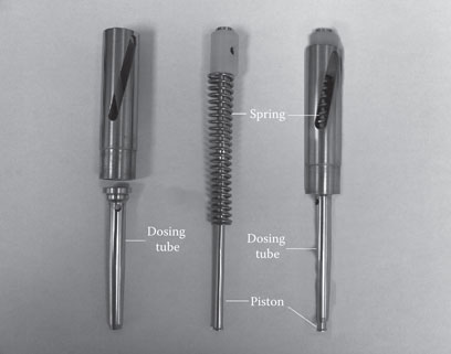
Figure 10.2Composition of a dosator.
Starting from Equation 10.1, the volume and density terms are modified to account for a cylindrical body (i.e., dosator) as follows:
 10.2
10.2where W is the dosator fill weight, Dpiston is the piston diameter, Hdosator is the powder height in dosator, ρbulk is the bulk powder density, and f1(ρ) is the precompression densification factor.
The first term in Equation 10.2 represents the volume of a cylinder. Piston widths vary for each capsule size; they can be directly measured or provided by machine vendors. Powder height in a dosator (Hdosator) is the minimum value of either the powder bed height (Hpowder) or the piston height (Hpiston) as shown in Equation 10.3:
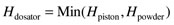 10.3
10.3where Hpowder is the powder bed height and Hpiston is the piston height in the dosator tube.
The second term in Equation 10.2 is related to powder density inside the dosator. This density is defined by the bulk powder density (bulk density of powder in the bowl) multiplied by a factor representing the extent of densification a powder is subjected to as a result of dosator immersion. This is one of two types of powder densifications achieved in a dosator.
Powder Densification inside a Dosator
Powder densification within a dosator is required for two reasons: first, densification helps form arches that support the powder’s weight and keep it in the dosator.25 Densification is also needed to fit a plug into the capsule body. There are two types of densification within a dosator: precompression and compression. The powder density within a dosator (ρdosator) is a cumulative value from both types as shown in Equation 10.4:
 10.4
10.4where ρdosator is the powder density within the dosator, ρbulk is the bulk powder density, f1(ρ) is the precompression densification factor, and f2(ρ) is the compression densification factor.
Precompression and compression densification factors are unitless factors with values ≥1, where unity represents no densification. If both factors equal unity, the density within a dosator reduces to the bulk powder density.
Precompression Densification Factor (f1(ρ))
The precompression densification factor reflects densification that occurs during dosator insertion into the powder bed when the powder height is more than the piston height (Hpowder > Hpiston). The extent of precompression densification is determined by the powder-to-piston height ratio and powder flow behavior. The more fluid the powder, the less the precompression densification. Precompression densification factor is defined by Equation 10.5:
 10.5
10.5where f1(ρ) is the precompression densification factor, F is the powder flow factor, Hpowder is the powder height in the powder bowl, and Hpiston is the piston height.
The powder flow factor (F) in Equation 10.5 is a unitless factor that is indicative of powder flow; it has an upper boundary limit of unity. A fluid powder will have a flow factor and f1(ρ) of unity, indicating no precompression is possible for such a powder.
Compression Densification Factor (f2(ρ))
Compression densification occurs from piston displacement against the powder after the dosator is immersed in the powder bed. This factor is defined by Equation 10.6:
 10.6
10.6where f2(ρ) is the compression densification factor, Hdosator is the powder height in the dosator (Equation 10.3), and Hplug is the plug height.
The plug height represents the powder height reached within the dosator as a result of piston displacement (ΔH):
 10.7
10.7where Hdosator is the powder height in the dosator (Equation 10.3) and ΔH is the piston displacement against powder (i.e., distance a piston moves against powder).
The actual plug heights are expected to be slightly larger than those predicted by Equation 10.7 because of plug expansion after ejection. The plug height (Hplug) is an important parameter to control during encapsulation; it should be equal to or less than the effective capsule body length (hCaps; Figure 10.3), which can be calculated using Equation 10.8:

Figure 10.3Schematic presentation of a plug inside the capsule body.
 10.8
10.8where hCaps is the effective capsule body length, h0 is the length of the cylindrical portion of the capsule body, h1 is the length of the spherical portion of the capsule body, and h2 is the length of dead space.
The effective capsule body length is higher than the cylindrical capsule body length because plugs have a smaller diameter than capsule bodies; therefore, the plug sinks in the spherical portion of the capsule body as shown in Figure 10.3. The effective capsule body length (hCaps) would equal the cylindrical length of the capsule body (h0) if the plug and capsule body widths were equal. The length of the dead space within a capsule is calculated using Equation 10.9:
 10.9
10.9where R is the cup radius (i.e., radius of the spherical segment) and a is the plug radius.
The dead space represents the space where no fill is present. Values for h0, h1, and R are obtained from capsule specifications provided by capsule vendors.
Piston Movement within a Dosator
Piston movement within a dosator is affected by two constraints: the spring and the powder.
The Spring Factor
At the maximum piston height, the spring within the dosator is at the most relaxed position; lowering the piston height in the dosator tube will involve spring compression. The actual height achieved is different from that set depending on the spring factor (k) as shown below:
 10.10
10.10where k is the spring factor, Hcom is the set piston displacement, and ΔH0 is the achieved piston displacement in an empty bowl.
The spring factor is a unitless number that is unique to that spring. If k = 1, then both set and achieved displacement values would be equal (ΔH0 = Hcom).
According to Figure 10.4, piston height (distance from the open end of a dosator to the piston tip) and its displacement (distance from the maximum piston height to the piston tip) are determined by the same spring, Therefore, the actual distance a piston moves is given by


Figure 10.4Schematic presentation of piston movement within a dosator (based on Zanasi machines).
 10.11
10.11where Hpiston is the piston height, Hpistonset is the set piston height, Hpistonmax
 is the maximum piston height, and k is the spring factor.
For example, for a dosator with a spring factor of 0.9 and a maximum piston height of 26 mm, if the set piston height was 16 mm, then the actual piston height would be 17 mm. This is important because it affects how much powder can be filled inside the dosator according to Equation 10.2.
Powder Compressibility
In addition to spring properties, the actual displacement achieved for a set value will depend on the compression resistance exhibited by the powder being compressed. Different powders have different compression properties; thus, achieved piston displacements will differ accordingly.
In the presence of powder, the actual distance traveled by the piston (i.e., piston displacement against powder) is related to the set value through the powder compression factor (X) as shown in Equation 10.12:
 10.12
10.12where X is the powder compression factor, Hcom is the set piston displacement, and ΔH is the achieved piston displacement against powder.
The powder compression factor is a unitless factor that is similar to the spring factor derived in Equation 10.10, except that it is measured in the presence of powder when the piston and powder heights are set to the maximum value (Hpowder=Hpiston=Hpistonmax) .25
.25
The powder compression factor (X) ≤ spring factor (k) because it accounts for the cumulative resistance to piston movement from both the spring and powder.
Equation 10.12 can be rearranged as
 10.13
10.13The more compressible the powder (i.e., higher X), the higher the actual piston displacement will be for a set compression. Equation 10.13 is a special case (Hpowder=Hpiston=Hpistonmax) of a general equation (Equation 10.14):
 10.14
10.14where Hcom is the set piston displacement, d0 is the starting point of displacement, d1 is the piston displacement against air, and X is the powder compression factor.
If the piston height and piston displacement settings are opposite settings controlled by the same spring (Figure 10.4), then the starting point of displacement (d0) represents the value below which no piston displacement occurs. The value of d0 depends on the difference between the maximum achievable piston height and set piston height according to Equation 10.15:
 10.15
10.15where Hpistonmax is the maximum piston height and Hpiston is the piston height determined from Equation 10.11.
Piston displacement against air (d1) represents the distance a piston moves within the dosator before contacting the powder (Figure 10.4); this occurs when the piston height is more than the powder height (Hpiston > Hpowder) as shown in Equation 10.16:
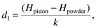 10.16
10.16where Hpiston is the piston height determined from Equation 10.11, Hpowder is the powder height in the powder bowl, and k is the spring factor.
For any densification to occur from piston displacement, the piston displacement setting (Hcom) should exceed d0 + d1.
Equation 10.14 is important as it relates the set piston displacement (Hcom) to that achieved against powder (ΔH), which is needed to calculate the plug height (i.e., plug length) according to Equation 10.7.
Stay updated, free articles. Join our Telegram channel

Full access? Get Clinical Tree


