Fig. 9.1
The compositional and functional differences between coated-type or joined-type composite and FGMs
The suitable properties for dental implant are shown in Fig. 9.2. For the case of uniform implant, the properties such as strength and biocompatibility are constant throughout the implant material. On the other hand, the implant with compositional gradient could control the functions of mechanical properties and biocompatibility, depending on the necessity of each part of implant, without the abrupt change due to the formation of discrete boundary [6]. Thus, the so-called trade-off relation can be overcome by the idea of FGMs.
Fig. 9.2
Suitable properties of functionally graded dental implant
Indeed, we can find many FGMs structures in nature; this is because biological systems such as plant stems and tree stems, animal bones, mollusk shells, and other biological hard tissues tend to be optimized for the loading conditions, to which they are subjected [5]. Human tissues have been also developed and remodeled in such a way to best adapt the function requirements. Consequently, the biological systems are complicated and non-uniform. For example, bamboo and certain other plants have excellent characters based on functionally graded structures [7]. Figure 9.3 shows a cross section of bamboo stem. The matrix of bamboo is filled by soft tissue cells called parenchymatous cells, and that is longitudinally reinforced by strong fibers called the vascular bundle sheath. Graded structure of the density, size, and shape of the vascular bundle sheath can be found along the radial direction.
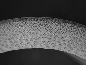
Fig. 9.3
Transversal cross section of bamboo stem
A number of FGMs fabrication methods have been proposed and comprehensive reports have been given on the general fabrication methods [3–5]. In general, there are three approaches to fabricate FGMs, as shown in Fig. 9.4. The first one is to eliminate the interface of coated-type or joined-type composite, eliminating discontinuities in the properties at the interface, as shown in Fig. 9.4a. Compositional gradient can be formed by elimination of the sharp interface by diffusion. The second one is to induce non-uniform distributions of dispersoids in a homogeneous particle composite, creating multiple functions within the material, as shown in Fig. 9.4b. One example is centrifugal method. In the centrifugal method, a centrifugal force applied to a homogeneous molten composite assists the formation of the desired gradation. The composition gradient is then achieved primarily due to the difference in the centrifugal force produced by the difference in density between the molten metal and solid particles [8]. The apparatus for the centrifugal method and motion of solid particles under the centrifugal force are shown in Fig. 9.5. The third one is carried out by sequential buildup of layers, as shown in Fig. 9.4c. Powder processing, thermal spray processing, chemical vapor deposition (CVD), and physical vapor deposition (PVD) are the typical examples.
Fig. 9.4
Three approaches to fabricate FGMs
Fig. 9.5
The apparatus for the centrifugal method and motion of solid particles under the centrifugal force
Fabrication of FGMs by the powder processing is schematically illustrated in Fig. 9.6. At first, material A and material B are weighed and mixed. Then, graded compacts are produced by sequentially layering the powder mixture in the die according to a predesigned spatial distribution of the composition. Finally, the sintering is carried out by hot isostatic pressing (HIP), pressureless sintering after cold isostatic pressing (CIP) compaction, hot press, and spark plasma sintering (SPS).
Fig. 9.6
Fabrication process of the FGMs by powder processing
In thermal spraying, feedstock material (coating precursor) is introduced into a combustion or plasma flame. The molten or semimolten micrometer-sized particles are accelerated toward substrates, and coatings are made by the accumulation of numerous sprayed particles. Since the deposit by the thermal spray processing is formed through the sequential buildup of layers, a number of approaches can be used to produce a graded deposit [9]. Figure 9.7a, b shows multiple feeder method and multiple torch method, respectively. In the case of multiple feeder method, material A and material B are simultaneously introduced into the plasma jet by changing the mixture ratio. On the other hand, in the case of multiple torch method, material A and material B are deposited through torch A and torch B, respectively, with optimum spray parameters for each material.
Fig. 9.7
Fabrication of the FGMs by thermal spray processing. (a) Multiple feeder method and (b) multiple torch method
Functionally graded biomaterials are also fabricated by several methods. For example, titanium nitride–apatite functionally graded implants are fabricated by SPS method [10]. It is reported that functionally graded Ti–HAP coatings on Ti–6Al–4V have been fabricated by chemical solution deposition [11]. Ti–TiC–C gradient biomaterial has been prepared by means of plasma source ion implant–ion beam enhanced deposition [12]. Functionally graded (Ca–Ti–O)-(Ca–P–O) bioceramic film is formed by metal organic chemical vapor deposition (MOCVD) method [13]. In this chapter, our recent experimental results, Ti/biodegradable-polymer FGMs for bone tissue fabricated by SPS method, continuous graded composition in Ti–ZrO2 bio-FGMs fabricated by mixed-powder pouring method, white ceramic coating on Ti–29Nb–13Ta–4.6Zr alloy for dental application, Al-based FGMs containing TiO2 nanoparticles with antibacterial activity by a centrifugal mixed-powder method, and magnetic graded materials by inhomogeneous heat treatment of SUS304 stainless steel will be introduced.
9.2 Ti/Biodegradable-Polymer FGMs for Bone Tissue Fabricated by SPS Method [14]
Ti and Ti alloys are widely used as metallic implants due to their excellent mechanical properties, corrosion resistance, and nontoxic behavior. However, the Young’s modulus of currently used Ti alloys (90–110 GPa) is still not ideal compared with that of human bone (10–20 GPa), which may lead to premature failure of the implant [15, 16]. Therefore, the low Young’s modulus Ti alloys are required to decrease the stress-shielding effect in bone implant coupling, enhancing bone regeneration and avoiding resorption process. In order to reduce the apparent elastic modulus of Ti and its alloys, recently, porous Ti and its alloys have been developing. Moreover although they are classified into bioinert materials, a conduction of living bone occurs on the surface of implanted materials that reside in the body for a long period. This can lead to refracture of cured bone in removal operations [17].
Meanwhile, poly-L-lactic acid (PLLA) has attracted much attention, because it is biodegradable, compostable, producible from renewable resources, and nontoxic to the human body and the environment [18]. If Ti-based biocomposites containing PLLA could be fabricated, the PLLA can be gradually decomposed inside the body with progress of time, and then the pore can be generated into the Ti matrix during repairing of the bone. Since the bone can simultaneously penetrate into the pore, the Ti matrix can be tightly bonded with the bone. However, there is a large difference of melting point between Ti and PLLA. Namely, the melting points of Ti and PLLA are 1,670 °C and around 170–180 °C, respectively. Therefore, the process of the Ti-based biocomposite containing PLLA must be done at relative lower temperature; as a result, the strength of the obtained composite becomes lower [19]. Alternatively, the space holder method is applied. Porosity is generated by removing the spacer that was sintered with the base material [20, 21]. Moreover, for the bulk mechanical property, fabricated Ti–PLLA composite must have lower Young’s modulus, while wear resistance around the surface must be improved. Such trade-off relation can be overcome by the concept of FGMs.
Prior to fabricating the Ti–PLLA FGMs, the Ti–NaCl composite was fabricated by SPS method using powder mixture of commercially pure (CP) Ti powder (under 56 μm) and NaCl (hexahedron shapes; some of the NaCl particle size was over 500 μm) to complete the sintering of Ti matrix, since the difference in melting points of these materials is relatively small. Volume fractions of NaCl powder were 30 vol%, 50 vol.%, and 70 vol.%. The Ti–NaCl powder mixture was sintered at 700 °C for 5 min under applied stress of 30 MPa. Figure 9.8a, b shows optical microscope (OM) images of Ti–30vol.%NaCl and Ti–70vol.%NaCl composites, respectively [14]. The upper and lower pictures were observed on plane Z0 and plane R, respectively. As can be seen in Fig. 9.8, oblate NaCl particles are observed on the plane R, whereas there is no anisotropic microstructure on the plane Z0. That is, NaCl particles are compressed during the SPS process.
Fig. 9.8
OM images of (a) Ti–30 vol.%NaCl and (b) Ti–70 vol.%NaCl composites at plane Z0 and plane R before dissolving NaCl particles (Reprinted from Ref. [14], Copyright 2011, with permission from Elsevier)
The Ti–NaCl composites were put into hot water of 100 °C to obtain porous Ti. Hereafter porous Ti samples obtained from Ti–30vol.%NaCl, Ti–50vol.%NaCl, and Ti–70vol.%NaCl composites by the dissolution process are abbreviated to porous Ti(30), porous Ti(50), and porous Ti(70), respectively. It is found that porous Ti(50) and porous Ti(70) samples have no remained NaCl particles, and porous Ti(50) and porous Ti(70) have open pores. Figure 9.9 shows the pore size distribution in the porous Ti(50) [14]. In these graphs, mean pore size range in the specimen distributes within 200–600 μm. It is reported that the optimal pore size in porous bone substitutes to obtain differentiation and growth of osteoblasts and vascularization is approximately 300–400 μm or 200–500 μm [22]. Thus, the obtained porous Ti is satisfied the basic requirement of biomedical pores of hard tissues.
Fig. 9.9
The pore size distributions in the porous Ti(50) at plane Z0 and plane R (Reprinted from Ref. [14], Copyright 2011, with permission from Elsevier)
Relationship between bulk density and porosity was investigated as shown in Fig. 9.10 [14]. As can be seen, the more porosity increased, the more density decreased linearly. Since the density of bone is 1.6–2.0 Mg/m3, the porous Ti(50) has closed value to the range of bone density. In addition, at least the most of all pores is supposed to be open pore and no residual NaCl remained in the bulk in Ti(50).
Fig. 9.10
Relationship between bulk density and porosity in porous Ti (Reprinted from Ref. [14], Copyright 2011, with permission from Elsevier)
Young’s modulus and 0.2 % proof stress of pure Ti and porous Ti samples are shown in Fig. 9.11a, b, respectively [14]. Young’s modulus and 0.2 % proof stress of samples are decreased with increasing volume fraction of pores (porosity). Moreover, anisotropy of these properties is found for porous Ti samples. Although Young’s modulus of pure Ti is close to the required one, 0.2 % proof stress of pure Ti is much larger than the required yield stress. On the other hand, Young’s modulus of the porous Ti(30) is smaller than the required modulus, and its 0.2 % proof stress is almost the same stress with ideal metallic implant material. From these results, it is found that porous Ti(30) can satisfy both requirements of Young’s modulus and yield stress as a metallic implant material by means of improving its Young’s modulus, although the porous Ti(30) does not have open pores. In addition, porous Ti(50) has open pores and it is likely to be able to satisfy the requirements by means of adding a reinforcement material into pores. Biodegradable material such as PLLA would be one of expectable materials as reinforcement filler.
Fig. 9.11
Young’s modulus and 0.2 % proof stress of pure Ti and porous Ti samples. Compression axes are along perpendicular (PE) and parallel (PA) direction (Reprinted from Ref. [14], Copyright 2011, with permission from Elsevier)
To fabricate the Ti–PLLA FGMs, porous Ti sample obtained from Ti–NaCl composites with 50 vol.% NaCl and PLLA pellets were mixed in recovery flask, and the flask was heated at about 200 °C to melt PLLA pellets. After porous Ti samples were covered with melted PLLA, an aspirator vacuumed the samples in the flask to remove the air in pores. Following the procedures, the flask was reverted to atmospheric pressure and then melting PLLA was introduced into the pores of porous Ti samples. Figure 9.12a, b shows OM micrographs showing the Ti–PLLA FGMs sample fabricated from porous Ti(50) at surface region (Plane Z0) and interior region (Plane Zh/3), respectively [14]. It seems that PLLA is successfully introduced into the Ti matrix. It must be noted here that some pores are observed on the Plane Zh/3 as shown in Fig. 9.12b, while there is no pore on Plane Z0 as shown in Fig. 9.12a. The amount of pore changes from place to place, and such porosity distribution could cause gradients of mechanical properties in the fabricated Ti–PLLA FGMs sample.
Fig. 9.12
OM images at (a) plane Z0 and (b) plane Zh/3 in Ti–PLLA FGMs sample fabricated from porous Ti(50) (Reprinted from Ref. [14], Copyright 2011, with permission from Elsevier)
Wear tests for fabricated Ti–PLLA FGMs sample were performed using a ball-on-disk-type machine, where the samples were slid along three different directions under reciprocal movement against a stationary counter sphere of stainless steel. The results are shown in Fig. 9.13, as well as that from porous Ti(50) [14]. It is seen that osmotic PLLA into porous Ti enhances its wear resistance. Since PLLA is much softer than Ti matrix, it is supposed that PLLA near worn surface was preferentially scraped out from the Ti–PLLA FGMs sample and subsequently spreads out and covers on the Ti matrix during friction. It is considered that preferential abrasion and coating of PLLA due to wear protects against wear of Ti matrix and reduces adhesion of counter-face with Ti.
Fig. 9.13
Results of wear tests sliding along three different directions under reciprocal movement (Reprinted from Ref. [14], Copyright 2011, with permission from Elsevier)
Young’s modulus and 0.2 % proof stress of porous Ti, Ti–NaCl composite, and Ti–PLLA FGMs sample with different parts are shown in Fig. 9.14a, b, respectively. As shown in Fig. 9.14a, the porous Ti(50) has the lowest Young’s modulus, since it has a porous structure. On the contrary, the highest Young’s modulus was observed for the pore-free Ti–NaCl composite, which is within the range of the modulus of the bone. Theoretical Young’s modulus of Ti–PLLA FGMs calculated by simple rule of mixture is also shown in this figure. It should be noted that the Young’s modulus values of Ti–PLLA FGMs samples from outer–outer and inner–outer positions were in excellent agreement with the theoretical one. 0.2 % proof stress of Ti–PLLA FGMs also changes from place to place. In this way, the mechanical property gradients are observed for Ti–PLLA FGMs, which may be caused by the volume fractional gradient of pores, as shown in Fig. 9.12. Since Young’s modulus and 0.2 % proof stress of the Ti–PLLA FGMs sample are close to the required ones, Ti–PLLA FGMs satisfy the required mechanical properties of metallic implant material by means of PLLA dispersion in porous Ti. It can be expected that optimum performance will be obtained just after implantation of the composite into the bone, and then PLLA will gradually degrade and be absorbed into the body. Although its mechanical properties will become lower as PLLA degrades, osteogenesis will occur in the pore instead.
Fig. 9.14
(a) Young’s modulus and (b) 0.2 % proof stress of porous Ti(50), Ti–50 vol.%NaCl composite and Ti–PLLA FGMs with different regions. Theoretical Young’s modulus of Ti–50 vol.%PLLA FGMs is also shown in (a) (Reprinted from Ref. [14], Copyright 2011, with permission from Elsevier)
9.3 Continuous Graded Composition in Ti–ZrO2 Bio-FGMs Fabricated by Mixed-Powder Pouring Method
In session 9.1, it is described that the powder processing has many advantages to fabricate the FGMs. However, the graded structure fabricated by the powder processing becomes stepwise structure, and it is, unfortunately, difficult to produce the FGMs with continuous gradients. By a centrifugal slurry method, this shortcoming can be overcome. For centrifugal slurry method, slurry with two types of solid particles will be used, namely, high-velocity particle with larger density and/or larger particle size and low-velocity particle with smaller density and/or smaller particle size, as shown in Fig. 9.15a [8, 23]. Since the motion of solid particles in viscous liquid under centrifugal force can be determined by the Stokes’ law, the terminal velocity is reached at a very early stage of the centrifugal casting method [24, 25]. Therefore, the velocity of particles within a liquid under centrifugal force, dx/dt, can be expressed as
where ρ p , ρ m , D p , G, g, and η are density of particle, density of liquid, particle diameter, G number showing the level of centrifugal force, gravitational acceleration, and apparent viscosity of liquid, respectively. The continuous gradient can be obtained by the difference of migration rate between the two kinds of particles, i.e., high-velocity particle and low-velocity particle, predicted by Eq. 9.1. After complete sedimentation occurs, the liquid part of the slurry will be removed, and a green body with continuous gradient can be obtained. The green body is, then, subjected to sintering, and finally an FGMs sample with continuous gradient can be fabricated.
(9.1)
Fig. 9.15


Fabrication process to obtain green body with continuous gradient under a centrifugal force. (a) Centrifugal slurry method [8] and (b) centrifugal slurry-pouring method [27]
Stay updated, free articles. Join our Telegram channel
Full access? Get Clinical Tree
