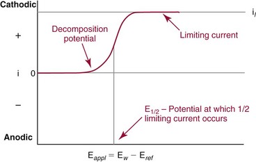
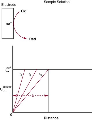
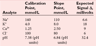
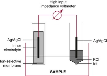
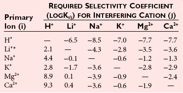
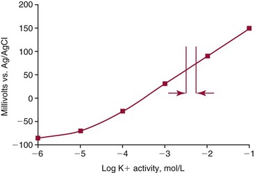
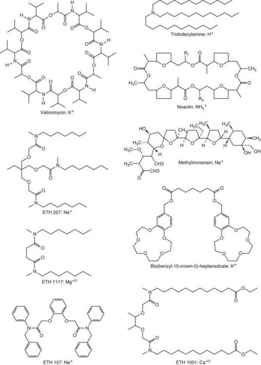
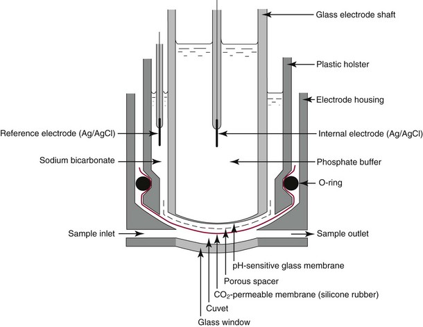
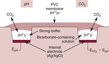
Chapter 11 Electrochemical and optical sensors (and associated biosensors) are firmly established in clinical analysis systems. Sensors for measurement of blood gases, electrolytes, and metabolites are particularly well suited for incorporation into automated, point-of-care, and critical-care analyzers (see Chapters 19, 20, and 28, respectively), because of their ease of use, low maintenance, and ability to measure clinically important analytes in undiluted blood.62 When integrated into chromatographic systems (see Chapter 13), electrochemical detectors provide a highly sensitive and selective means of detecting a variety of other analytes, such as therapeutic drugs, neurotransmitters, glutathione, and homocysteine. Also, electrochemical detection has been applied successfully for monitoring coagulation reactions, detecting toxic lead in blood samples, and developing novel ultrasensitive immunoassays. When bioelements are integrated with electrodes, the resultant biosensors further expand the analytical capabilities of such devices. In addition, the development and application of optodes, based on some of the same selective chemistries used in electrochemical devices, have resulted in another analytical tool for measuring blood gases and electrolytes. Potentiometry is the measurement of an electrical potential difference between two electrodes (half-cells) in an electrochemical cell (Figure 11-1) when the cell current is zero (galvanic cell). Such a cell consists of two electrodes (electron and metallic conductors) that are connected by an electrolyte solution (ion conductor). An electrode, or half-cell, consists of a single metallic conductor that is in contact with an electrolyte solution. Ion conductors have been composed of one or more phases that are either in direct contact with each other or separated by membranes permeable only to specific cations or anions (see Figure 11-1). One of the electrolyte solutions is the unknown or test solution; this solution may be replaced by an appropriate reference solution for calibration purposes. By convention, the cell notation is shown so that the left electrode (ML) is the reference electrode, and the right electrode (MR) is the indicator (measuring) electrode [see later equation (3)].11 Redox potentials are the result of chemical equilibria involving electron transfer reactions: In an electrochemical cell, electrons may be accepted from or donated to an inert metallic conductor (e.g., platinum). A reduction process tends to charge the electrode positively (remove electrons), and an oxidation process tends to charge the electrode negatively (add electrons). By convention, a heterogeneous redox equilibrium [equation (2)] is represented by the cell E = electrode potential of the half-cell E0 = standard electrode potential when aRed/aOx = 1 n = number of electrons involved in the reduction reaction N = (R × T × ln 10)/F (the Nernst factor if n = 1) R = gas constant (= 8.31431 Joules × K−1 × mol−1) T = absolute temperature (unit: K, kelvin) F = Faraday constant (= 96,487 Coulombs × mol−1) ln 10 = natural logarithm of 10 = 2.303 aRed/aOx = product of mass action for the reduction reaction The electrode potential is given by E0 = 0 at all temperatures (by convention) fH2 = fugacity of hydrogen gas aH+ = activity of hydrogen ions Because AgCl and Ag are both solids, their activities are equal to unity (aAgCl = a0Ag = 1). Therefore, from equation (9), the half-cell potential is controlled by the activity of chloride ion in solution (aCl−) contacting the electrode. The Ag/AgCl electrode is used both as an internal reference element in potentiometric ion-selective electrodes (ISEs) and as an external reference electrode half-cell of constant potential, required to complete a potentiometric cell (see Figure 11-1). In both cases, the Ag/AgCl electrode must be in equilibrium with a solution of constant chloride ion activity. The Ag/AgCl element of the external reference electrode half-cell is in contact with a high-concentration solution of a soluble chloride salt. Saturated potassium chloride is commonly used. A porous membrane or frit is frequently employed to separate the concentrated KCl from the sample solution. The frit serves both as a mechanical barrier to hold the concentrated electrolyte within the electrode and as a diffusional barrier to prevent proteins and other species in the sample from coming into contact with the internal Ag/AgCl element, which could poison and alter its potential. The interface between two dissimilar electrolytes (concentrated KCl/calibrator or sample) occurs within the frit and develops the liquid-liquid junction potential (Ej), a source of error in potentiometric measurements. The difference in liquid-liquid junction potential between calibrator and sample (residual liquid junction potential) is responsible for this error and can be minimized and usually neglected in practice if the compositions of the calibrating solutions are matched as closely as possible to the sample with respect to ionic content and ionic strength. An equitransferant electrolyte at high concentration as the reference electrolyte further helps to minimize the residual liquid junction potential. Potassium chloride at a concentration ≥2 mol/L is preferred. Differences of approximately −2% in the measurement of sodium by ISEs have been demonstrated when the KCl concentration in the reference electrolyte is lowered from 3 to 0.5 mol/L.28 The magnitude of the residual liquid junction potential may also be estimated by the Henderson equation106 with sufficient knowledge of ionic activities, ionic charges, and ionic mobilities for each electrolyte on both sides of the junction and the temperature. Using this estimate, a correction to the overall cell potential may be applied. The presence of erythrocytes in the sample may affect the magnitude of the residual liquid junction potential in a less predictable manner. For example, erythrocytes in blood of normal hematocrit are estimated to produce approximately 1.8 mmol/L positive error in the measurement of sodium by ISEs when an open, unrestricted liquid-liquid junction is used.13 This bias may be minimized if a restrictive membrane or frit is used to modify the liquid-liquid junction. ai = activity of the ion of interest aj = activity of the interfering ion Ki/j = selectivity coefficient for the primary ion over the interfering ion. Low values indicate good selectivity for the analyte i over the interfering ion j All other terms are identical to those in the Nernst equation [equation (4)]. Various approaches may be used to determine the selectivity of an ISE for a primary ion over an interfering ion.7,14 A straightforward approach is the separate solution method, whereby the potential of an ISE is determined in solutions of the primary and interfering ions separately, but at equal ionic activities. The selectivity coefficient is then calculated as follows: Most ISEs used in clinical practice have sufficient selectivity and do not require correction for interfering ions. Oesch and associates have published required ISE selectivity coefficients for ions commonly measured in clinical chemistry over other ions found in blood.88 Table 11-1 shows required selectivity coefficients for the measurement of cations of interest in clinical chemistry over potentially interfering cations, assuming an acceptable maximum interference of 1% for the ion of interest. Glass membrane electrodes are employed to measure pH and Na+, and as an internal transducer for PCO2 sensors. The H+ response of thin glass membranes was first demonstrated in 1906 by Cremer.26 In the 1930s, practical application of this phenomenon for measurement of acidity in lemon juice was made possible by the invention of the pH meter by Arnold Beckman.11 Glass electrode membranes are formulated from melts of silicon and/or aluminum oxide mixed with oxides of alkaline earth or alkali metal cations. By varying the glass composition, electrodes with selectivity for H+, Na+, K+, Li+, Rb+, Cs+, Ag+, Tl+, and NH4+ have been demonstrated.33 However, glass electrodes for H+ and Na+ are today the only types with sufficient selectivity over interfering ions to allow practical application in clinical chemistry. A typical formulation for H+ selective glass is 72% SiO2; 22% Na2O; 6% CaO, which has a selectivity order of H+ Mechanisms of response of these ISEs fall into three categories: (1) charged, dissociated ion exchanger; (2) charged associated carrier; and (3) neutral ion carrier (ionophore).6,15 An early charged-associated ion-exchanger type ISE for Ca2+ was developed and commercialized for clinical application in the 1960s based on the Ca2+-selective ion-exchange/complexation properties of 2-ethylhexyl phosphoric acid dissolved in dioctyl phenyl phosphonate.37 A porous membrane was impregnated with this cocktail and mounted at the end of an electrode body. This type of sensor was referred to as the “liquid membrane” ISE. Later, a method was devised whereby these ingredients could be cast into a plasticized poly(vinyl chloride) (PVC) membrane that was more rugged and convenient to use. This same approach is still used today to formulate PVC-based ISEs for clinical use.84 A major breakthrough in the development and routine application of PVC-type ISEs was the discovery by Simon and coworkers that the neutral antibiotic valinomycin could be incorporated into organic liquid membranes (and later plasticized PVC membranes), resulting in a sensor with high selectivity for K+ over Na+ (KK/Na = 2.5 × 10⁻⁴).97 The K+ ISE based on valinomycin was the first example of a neutral carrier ISE and is used extensively today for the routine measurement of K+ in blood. Figure 11-2 shows the response of the valinomycin-based K+ ISE in the presence of physiologic concentrations of Na+, Ca2+, and Mg2+. The wide linear range of this ISE over three orders of magnitude makes it suitable for the measurement of K+ in blood and urine. The K+ range in blood is only a small portion of the electrode linear range and is spanned by a total ΔEMF of about 9 mV. Interference from other cations, seen as deviation from linearity, is not apparent at K+ activities >10−4 mol/L. Other, less selective polymer-based ISEs (e.g., for the measurement of Mg2+ and Li+) are subject to interference from Ca2+/Na+ and Na+, respectively, requiring simultaneous determination and correction for the presence of significant concentrations of interfering ions.81,99 Studies regarding the relationship between molecular structure and ionic selectivity have resulted in the development of polymer-based ISEs using a number of naturally occurring and synthetic ionophores, with sufficient selectivity for application in clinical analysis. The chemical structures of several of these neutral ionophores are illustrated in Figure 11-3. Dissociated anion exchanger-based electrodes employing lipophilic quaternary ammonium salts as active membrane components are still used commercially for the determination of Cl− in whole blood, serum, and plasma despite some limitations.68 Selectivity for this type of ISE is controlled by extraction of the ion into the organic membrane phase and is a function of the lipophilic character of the ion (because, unlike with the carriers described earlier, no direct binding interaction occurs between the exchanger site and the anion in the membrane phase). Thus, the selectivity order for Cl− ISE based on an anion exchanger is fixed as R− > ClO4− > I− > NO3− > Br− > Cl− >F−. Application of the Cl− ion-exchange electrode therefore is limited to samples without significant concentrations of anions more lipophilic than Cl−. Blood samples containing salicylate or thiocyanate, for example, will produce positive interference for the measurement of Cl−. Repeated exposure of the electrode to the anticoagulant heparin will lead to loss of electrode sensitivity toward Cl− because of extraction of negatively charged heparin into the membrane. Indeed, this extraction process has been used successfully to devise a method to detect heparin concentrations in blood by potentiometry,75 as well as to develop a simple potentiometric technique to screen for the presence of toxic, high charge density polyanion contaminants (e.g., oversulfated chondroitin sulfate) in biomedical grade heparin preparations.127 High selectivity for carbonate anion can be achieved using a neutral carrier ionophore possessing trifluoroacetophenone groups doped within a polymeric membrane.65,107 Such ionophores form negatively charged adducts with carbonate anions, and the resulting electrodes have proven useful in commercial instruments for determination of total carbon dioxide in serum/plasma, after dilution of the blood to a pH value in the range of 8.5 to 9.0, where a significant fraction of total carbon dioxide will exist as carbonate anions. The plasticizer is crucial in controlling the polarity of the membrane and thus, along with the ionophore, plays a pivotal role in determining the selectivity of the membrane toward the ion of interest. A large lipophilic anion (e.g., tetraphenylborate derivative) is often included as an additive for preparation of cation-selective ISE membranes. This anion serves as a counteranion for the cation of interest as it is extracted into the membrane phase, forming a positively charged complex with the neutral ionophore. However, it is the ratio of bound to unbound ionophore sites at the membrane surface that determines the magnitude of the phase boundary potential generated by the ISE membrane.3 Thus, the selective response to the activity of the ion of interest is an interfacial property of the given ISE membrane. Studies have demonstrated that the ultimate detection limits of polymer membrane–type ISEs are controlled in part by the leakage of analyte ions from the internal solution to the outer surface of the membrane, and into the sample phase in close contact with the membrane.78 Hence, lower limits of detection can be achieved by decreasing the concentration of the primary analyte ion within the internal solution of the electrode. Further, this leakage of analyte ions, coupled with an ion-exchange process at the membrane sample interface when the selectivity of the membrane over other ions is assessed, can often yield a measured potentiometric selectivity coefficient that underestimates the true selectivity of the membrane. To determine “unbiased” selectivity coefficients by the separate solution method, the membrane should not be exposed to the analyte ion for extended periods of time, and the concentration of analyte ion in the internal solution should be low.8 To avoid leakage of primary ions from the inner solution of conventional polymer membrane ISEs, new more stable designs for solid-state ion sensors have been suggested, in which the ionophore-doped polymer ion-sensing membrane [based on more water repellent poly(methylmethacrylate)/poly(decylmethacrylate copolymer)] is coated onto a conductive poly(3-octylethiophene 2,5-diyl) (POT) polymer layer on the surface of an underlying gold electrode.121 An interesting application of sodium selective polymer (or glass) membrane electrodes is seen in the determination of whole blood hematrocrit.58 Because intracellular sodium concentrations are much lower than those in the plasma phase, the change in sodium concentration (dilution) measured potentiometrically before and after erythrocyte lysis can be used to assess the hematocrit of the blood sample. This approach can be coupled with simultaneous measurement of changes in potassium ion concentration as determined with a valinomycin-based polymer membrane ISE to quantify the concentration of potassium ions within red blood cells.96 Electrodes have been developed to measure PCO2 in body fluids. The first PCO2 electrode, developed in the 1950s by Stow and Severinghaus, used a glass pH electrode as the internal element in a potentiometric cell for measurement of the partial pressure of carbon dioxide.4 This important development paved the way for commercial availability of the three-channel blood analyzer (pH, PCO2, PO2) to give the complete picture of the oxygenation and acid-base status of blood. Figure 11-4 shows a diagram of a typical Severinghaus-style electrode for PCO2. A thin membrane (≈20 µm), permeable only to gases and water vapor, is in contact with the sample. Membranes of silicone rubber, Teflon, and other polymeric materials are suitable for this purpose. On the opposite side of the membrane is a thin electrolyte layer consisting of a weak bicarbonate salt (about 5 mmol/L) and a chloride salt. A pH electrode and an Ag/AgCl reference electrode are in contact with this solution. The PCO2 electrode is a self-contained potentiometric cell. Carbon dioxide gas from the sample or calibration matrix diffuses through the membrane and dissolves in the internal electrolyte layer. Carbonic acid is formed and dissociates, shifting the pH of the bicarbonate solution in the internal layer as follows: A slightly different potentiometric cell for PCO2 is shown in Figure 11-5. This cell arrangement uses two PVC-type pH-selective electrodes in a differential mode. The electrode membranes contain a lipophilic amine-type neutral ionophore that exhibits very high selectivity for H+ (see Figure 11-3). One electrode has an internal layer that is buffered, and the other is unbuffered, consisting of a low concentration of bicarbonate salt. Carbon dioxide gas from the sample or calibration matrix diffuses across the outer H+-selective PVC membranes of both sensors. On the unbuffered side, CO2 diffusion produces a potential shift at the internal interface of the pH-responsive membrane proportional to sample PCO2 concentration. The signal at the electrode with the buffered internal layer is unaffected by CO2 that diffuses across the membrane. Consequently, one half of the sensor responds to pH alone, and the other half responds to both pH and PCO2. The signal difference between the two electrodes cancels any contribution of sample pH to the overall measured cell potential. The differential signal is proportional only to PCO2. Unlike the traditional Severinghaus-style electrode, this differential potentiometric cell PCO2 sensor has been commercialized in a planar format and is more easily adaptable to mass production in sensor arrays.16 where ρH2O is the mass concentration of water in kg/L. For normal blood plasma, the mass concentration of water is approximately 0.93 kg/L, but in specimens with elevated lipids or protein, the value may be as low as 0.8 kg/L. In these specimens, the difference between concentration and molality may be as great as 20%. A significant advantage of direct potentiometry by ISE for the measurement of electrolytes is that the technique is sensitive to molality and therefore is not affected by variations in the concentration of protein or lipids in the sample. Techniques such as flame photometry, ISE methods requiring sample dilution (also called indirect potentiometry), and other photometric methods requiring sample dilution are affected by the presence of protein and lipids. In these methods, only the water phase of the sample is diluted, producing results lower than molality as a function of the concentration of protein and lipids in the sample. Thus there is a risk for errors, such as a falsely low Na+ concentration (pseudohyponatremia), in cases of extremely elevated protein and lipid concentrations (see also Chapter 28).2 where A and B are temperature-dependent constants (A = 0.5213 and B = 3.305 in water at 37 °C), a is the ion size parameter for a specific ion, and I is the ionic strength (I = 0.5 Σm × z2, where z is the charge number of the ions). Equation (16) shows that a decrease in the activity coefficient occurs with an increase in ionic strength. This effect is more pronounced when the charge (z) of the ion is high. Activity coefficients for ions in biological fluids, such as blood and serum, are difficult to calculate with accuracy because of the uncertain contribution of macromolecular ions, such as proteins, to the overall ionic strength. However, assuming that the normal ionic strength of blood plasma is 0.160 mol/kg, estimates of activity coefficients at 37 °C are as follows: Na+ = 0.75, K+ = 0.74, and Ca2+ = 0.31. Referring to equation (15), activity and concentration will differ greatly in samples of physiologic ionic strength, especially for divalent ions. Physiologically, ionic activity is assumed to be more relevant than concentration when chemical equilibria or biological processes are considered. Practically, however, ionic concentration is the more familiar term in clinical practice, forming the basis of reference intervals and medical decision concentrations for electrolytes. Early in the evolution of ISEs as practical tools in clinical chemistry, it was decided that changing clinical reference intervals to a system based on activity instead of concentration was impractical and carried the risk for clinical misinterpretation. A pragmatic approach for using ISEs in modern analyzers without changing established concentration-based reference intervals is to formulate calibration solutions with ionic strengths and ionic compositions as close as possible to those of blood plasma. In this way, the activity coefficient of each ion in the calibrating solutions approximates that in the sample matrix, allowing calibration and measurement of electrolytes in units of concentration instead of activity.90 A typical set of solutions for multi-ISE calibration in an analyzer is shown in Table 11-2. Two points are used to calibrate each ISE. The difference in the cell potential generated by these two solutions (ΔE) is used to calculate the response slope of the cell (slope = ΔE/Δlog c), where c is the concentration of ion in each calibrating solution, substituted for activity. The standard electrode potential, E0, is calculated as the y-intercept. Determination of ion concentration in an unknown sample is then a straightforward solution of the Nickolsky-Eisenman equation [equation (10)], after the cell potential generated by the sample is measured. TABLE 11-2 Examples of Two-Value Calibrating Solutions for Measurement of pH and Electrolytes by Direct Potentiometry* *Ionic strength adjusted to 160 mmol/kg with buffer salts and inert electrolytes. Calibration of the cell is done in units of concentration; however, as mentioned earlier, direct potentiometry is sensitive to the molality of the ion, which is related to concentration by the water content of the sample [equation (14)]. The water content of aqueous calibrating solutions shown in Table 11-2 is approximately 0.99 kg/L. The water content of normal blood plasma is ≈0.93 kg/L. Molality is 7% greater than concentration in this normal plasma specimen. The direct potentiometric cell will report results approximately 6% greater than the concentration in normal specimens because of this difference in water content between sample and calibrator (0.99/0.93 = 1.06). Direct potentiometry presents an advantage in that the technique is not affected by the presence of protein and lipids in the sample; however, the application of clinical reference intervals based on concentration again poses a risk for confusion and clinical misinterpretation. Most manufacturers of electrolyte measurement systems have overcome this problem in a practical way by following Clinical and Laboratory Standards Institute (CLSI) guidelines recommending the use of correlation factors to standardize ISE measurements to units of concentration. These factors may be obtained by standardizing the ISE measurement to certified reference materials based on human serum, with electrolyte values assigned in units of concentration.21,22,49 Appropriate correlation factors are then applied to sample calculations using algorithms resident in the instrument software. For electrolytic cells that form the basis of voltammetric and amperometric methods. where Ecell is the thermodynamic potential between the working and reference electrodes in the absence of an applied external voltage. When the external voltage is greater or less than this equilibrium potential, plus or minus any overpotential (η), then current will flow because of an oxidation or reduction reaction at the working electrode. A voltammogram is simply the plot of observed current, i, versus Eappl (Figure 11-6). In amperometry (see later), a fixed voltage is applied and the resulting current is monitored. The amount of current is inversely related to the resistance of the electrolyte solution and to any “apparent” resistance that develops because of mass transfer of the analyte species to the surface of the working electrode. Because electrochemical reactions are heterogeneous, occurring only at the surface of the working electrode, the amount of current observed is also highly dependent on the surface area (A) of the working electrode. When a potential is applied to a working electrode that will oxidize or reduce a species in the solution phase contacting the electrode, the electrochemical reaction causes the concentration of electroactive species to decrease at the surface of the electrode (Figure 11-7), a process termed concentration polarization. This in turn causes a concentration gradient of analyte species between the bulk sample solution and the surface of the electrode.35 When the bulk solution is stirred, the diffusion layer of analyte grows out from the surface of the electrode very quickly to a fixed distance controlled by how vigorously the solution is stirred. This diffusion layer is termed the Nernst layer and has a finite thickness (δ) after a relatively short time period (see Figure 11-7) when the solution is moving (convection). Voltammetry carried out in the presence of convection (by stirring the solution, rotating the electrode, flowing solution by electrode, etc.) is called steady-state voltammetry. When the solution is not moving, the diffusion layer grows further and further with time (i.e., not constant), creating larger and larger In steady-state voltammetry, when the potential of the working electrode is scanned past a value that will cause an electrochemical reaction, the current will rise rapidly and then will plateau, even as Eappl changes further. Figure 11-6 illustrates such a wave for a hypothetical reduction of an oxidized species (Ox) via an n electron reduction to a reduced species (Red). When the applied potential is much more negative than required, the current reaches a limiting value (termed the limiting current, il). This limiting current is proportional to the concentration of the electroactive species (Ox in this case) as expressed by the following equation: where i is the measured current in amperes, n equals the number of electrons in the electrochemical reaction (reduction in this case), F is Faraday’s constant (96,487 coulombs/mol), A is the electrochemical surface area of the working electrode (in cm2) (assuming a planar electrode geometry), D is the diffusion coefficient (in cm2/sec) of the electroactive species (Ox in this case), In voltammetric methods, the Eappl is varying via some waveform to alter the working electrode potential as a function of time and the resulting current measured. The current change occurs at the decomposition potential range, which is best when specific for a given analyte. However, the location of the current response as a function of Eappl provides information on the nature of the species present (e.g., E1/2), along with a concentration-dependent signal. This scan of Eappl can be linear (linear sweep voltammetry) or it can have more complex shapes that enable greatly enhanced sensitivity to be achieved for monitoring the concentration of a given electroactive species (e.g., normal pulsed voltammetry, differential pulse voltammetry, square wave voltammetry).91 When a dropping mercury electrode (DME) is used, such voltammetric methods are considered polarographic methods of analysis.
Electrochemistry and Chemical Sensors
Potentiometry and Ion-Selective Electrodes
Basic Concepts
Types of Electrodes
Redox Electrodes
Inert Metal Electrodes
Metal Electrodes Participating in Redox Reactions
Ion-Selective Electrodes
The Glass Electrode
 > Na+ > K+. This glass membrane has sufficient selectivity for H+ over Na+ to allow error-free measurements of pH in the range of 7.0 to 8.0 [[H+] = 10−7 to 10−8 mol/L] in the presence of >0.1 mol/L Na+. Glass pH electrodes with selectivity coefficients (KH/Na) over Na+ of 10−7 and better have been realized. By altering slightly the formulation of the glass membrane to 71% SiO2; 11% Na2O; 18% Al2O3, its selectivity order becomes H+ > Na+ > K+. Thus, the preference of the glass membrane for H+ over Na+ is greatly reduced, resulting in a practical sensor for Na+ at pH values typically found in blood.32
Polymer Membrane Electrodes
Electrodes for PCO2
Direct Potentiometry by ISE—Units of Measure and Reporting for Clinical Applications
Voltammetry/Amperometry
Basic Concepts
 values over time. This is termed non–steady-state voltammetry and often results in peak currents in i versus Eappl plots for electrolytic cells.
 is the diffusion layer thickness (in cm), and C is the concentration of the analyte species in mol/cm3. The D/δ term is often denoted as mo, the mass transfer coefficient of the Ox species to the surface of the working electrode. Note that equation (18) indicates a linear relationship for limiting current and concentration. The exact same equation applies for detecting reduced species by an oxidation reaction at the working electrode. In this case, by convention, the resulting anodic current is considered a negative current. As shown in Figure 11-6, the potential of the working electrode that corresponds to a current that is exactly one half the limiting current is termed the E1/2 value. This value is not dependent on analyte concentration. The E1/2 is determined by the thermodynamics (E0) of the given redox reaction, the solution conditions (e.g., if protons are involved in reaction, then the pH will influence the E1/2 value), and any overpotential caused by slow electron transfer, etc., at a particular working electrode surface. The E1/2 values are indicative of a given species undergoing an electrochemical reaction under specified conditions; hence, the E1/2 values enable one to distinguish one electroactive species from another in the same sample. If the E1/2 values for various species differ significantly (e.g., >120 mV), then measurements of several limiting currents in a given voltammogram can yield quantitative results for several different species simultaneously.
![]()
Stay updated, free articles. Join our Telegram channel

Full access? Get Clinical Tree


Basicmedical Key
Fastest Basicmedical Insight Engine


 Red; defined by the E0 value for that reaction (standard reduction potential)] and the kinetics for heterogeneous electron transfer at the interface of the working electrode. Often, slow kinetics of electron transfer for the redox reaction on a given inert working electrode (Pt, carbon, gold, etc.) mandates use of a much more negative (for reductions) or positive (for oxidations) Eappl than predicted based merely on the E0 for a given redox reaction. This is called an overpotential (η). Regardless of whether an overpotential for electron transfer exists, a specific oxidation or reduction reaction occurs at the surface of the working electrode in voltammetry/amperometry, and it is the charge transfer at this interface (current flow) that provides the analytical information.