Chapter Seven Electricity and magnetism
CHECK YOUR EXISTING KNOWLEDGE
Introduction
Until 1800, when Alessandro Volta succeeded in making a battery using plates of zinc and silver interspersed with damp cardboard, the study of electricity had been confined to electrostatics, the physics of static charges. Pioneering physicists such as Priestly, Coulomb, Poisson and Faraday had succeeded in showing that both static electricity and magnetism followed the same inverse square law as gravity; in this case known as Coulomb’s Law.
Electromagnetism
As protons have a positive charge and are spinning, this means they must also have a magnetic field associated with them: effectively a ‘north pole’ and a ‘south pole’, just like a miniature Earth, which, in turn, has a magnetic field generated by its spinning iron core. By contrast, the moon – which has no such core and is no longer spinning – has no magnetic field.
Fortunately, the body is replete with free protons – hydrogen ions. Indeed, with its ubiquitous presence in organic and water molecules, hydrogen is easily the most common atom (and ion) found in our bodies and the principle that has just been described is that behind the working of an MRI (magnetic resonance imaging) machine (of which more in Chapter 9).
In this chapter, we will be looking at electricity and magnetism; electromagnetism is explored in depth in Chapter 8.
Electrostatics
The laws that govern static charges can be summarized very simply:
The size of the attraction or repulsion is governed by…
here Q1 and Q2 are the size of the respective charges and d is their separation.
One hundred-and-fifty years ago, physicians had no such luxuries. I have, in the corner of my consulting room, a reminder that for our predecessors even something as simple as getting sufficient illumination to make an adequate examination could be a major challenge. The doctor’s double oil lamp (Fig. 7.1), came with two lamps, each with a double burner, mounted on pivoted arms so the full force of the light could, when required, be brought to bear on the patient. I have tried the lamp – it produced, I would estimate, the equivalent of a 5 watt bulb and had the added disadvantage of setting off the (electric) fire alarms.
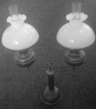
Figure 7.1 • A doctor’s oil lamp, circa 1860, with two double-wicked burners mounted on pivoting arms.
Electric potential
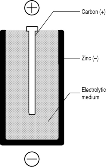
You will (hopefully) recall from Chapter 2 that potential energy is energy that has been stored. A system with potential energy has the capacity to do work when the stored energy is released. A convenient source of this potential energy is the battery or electric cell (Fig. 7.2).
Conductors and insulators
Although it is tempting to think of the material world as being divided into two – those substances that do conduct electricity and those (insulators) that do not – the true picture is more complex by far. We have talked about connecting an electric potential to an electric cable in order to obtain a current but the results we get will be very different, depending on the material from which the cable is made.
Conductors
Insulators
Materials that do not readily conduct electricity are termed insulators. In reality, they may be regarded as being at the opposite end of a spectrum that starts with superconductors: insulators are in fact merely conductors with extremely high resistivity. Typical examples of such materials are glass, rubber and the plastics that coat electrical cables so that they may be handled without the inadvertent transfer of electricity to the electrician – the classic electric shock! With insulators, the outer electrons are tightly bound to the atoms and are therefore not available to carry charge: the higher the binding energy, the better the insulator.
Electrodynamics
The study of moving charges is known as electrodynamics. For our purposes, this will comprise a study of the way in which electricity and electrical components work. This will enable us to understand the operation of such devices as we encounter and rely on in our clinical practice. Clinical tools such as the ophthalmoscope; diagnostic imaging of all types, be it ultrasound, magnetic resonance imaging, conventional x-rays or cutting edge proton emission tomography; and therapeutic interventions such as interferential or TENS machines all rely upon one common factor, the flow of electricity.
Circuit diagrams
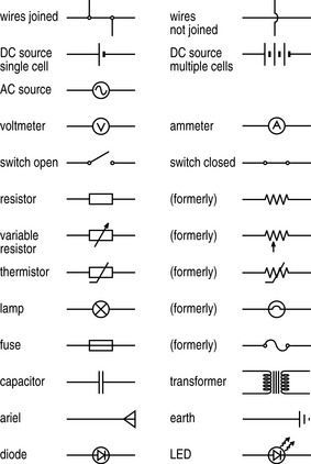
This flow of electricity through a conductive device or apparatus can be best described using a circuit diagram. This is the electrical equivalent of a map and, like a map, it utilizes symbols to describe the topography through which the electricity flows. The most common symbols – and certainly all those you are likely to encounter in the course of your studies and subsequent clinical career – are detailed in Figure 7.4.
Current
This flow of electrons is called a current, I, and is measured in amperes (amps; A), one of the seven basic SI units that, as you may recall from Table 1.1, is defined as:
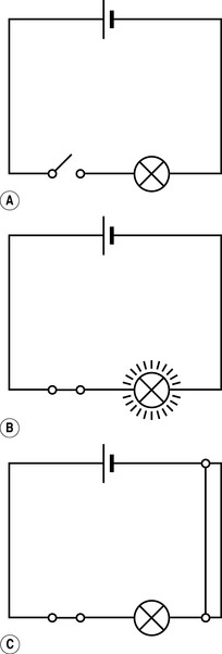
In order for a current to flow, there must be a continuous circuit running out from and back to the source of the electric potential: electrons will then flow down the potential gradient (Fig. 7.5). If there is a break in the circuit then no current will flow (this is how a switch works). Current flow can also be disrupted by a short circuit (where two wires within the circuit touch in such a way that the continuous flow of electrons is broken).
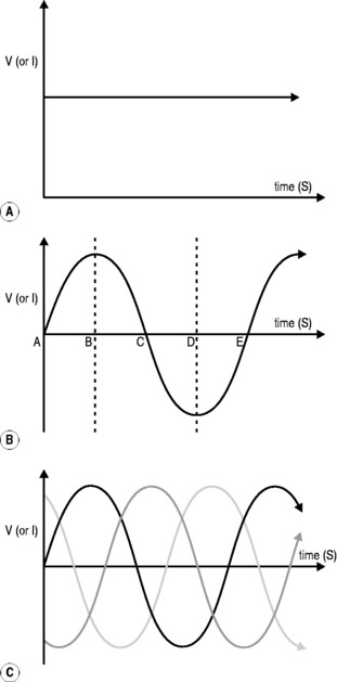
The type of current provided by a battery gives a continuous flow of electrons (Fig. 7.6A), at least until the battery becomes ‘flat’ when its charge is exhausted. Unfortunately, this direct current is limited in its ability to be generated and transmitted over long distances, which is why domestic electricity comes in a different form, known as alternating current (Fig. 7.6B).
Stay updated, free articles. Join our Telegram channel

Full access? Get Clinical Tree


 Fact File
 Fact File
 Fact File
 DICTIONARY DEFINITION
 CLINICAL FOCUS
 CLINICAL FOCUS