Chapter Three Applied physics
CHECK YOUR EXISTING KNOWLEDGE
Levers, beams and moments

For example, if an object weighs 30 N but the lever allows a person to move it using just 5 N (Fig. 3.1):
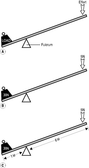

If a system is 100% efficient, which, of course, is only ever hypothetically possible, then these two factors will balance each other out: moving the load using the lever in Figure 3.1 will require only 1/6 of the effort but the load will only move 1/6 of the distance compared with the effort.
 Fact File
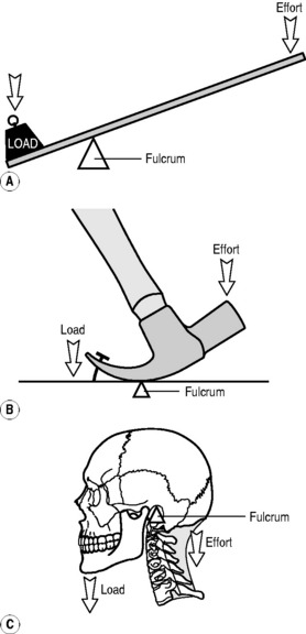
First order lever
These are the type of system that most people envisage when the word ‘lever’ is mentioned – a crowbar moving a heavy rock is an example of a first order lever whereby the fulcrum lies between the effort and the load (Fig. 3.2). Other examples include a children’s seesaw, pliers cutting a wire or a claw hammer pulling out a nail.
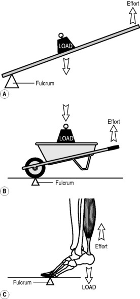
Second order lever
In this type of system, the load lies between the effort and the fulcrum (Fig. 3.3). The most obvious example of such an arrangement is the wheelbarrow: the pivot is the wheel axle; the load is in the barrow and the effort applied to the handles. Again, this is not usually a practical arrangement for the musculoskeletal system; however, one example of a second order system is the action of the gastrocnemius and soleus muscles on the foot and ankle. When we stand on tiptoe, the load is transmitted via the ankle joint, the pivot is the metatarsophalangeal joints and the effort is applied via the tendinous insertion of the muscles into the calcaneus (the Achilles’ tendon), which lies posterior to the ankle joint.
Muscle action
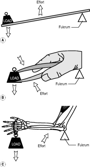
Not all muscles act directly on the bones they move to articulate a given joint. Although most do – called direct action – there are muscles that precipitate movement indirectly, called indirect action. Examples of direct action are seen all over the body: think of the action of biceps brachialis (Fig. 3.4) as a classic example. Some muscles, however, do not insert directly in to the two bones that they articulate. Perhaps the best – and most easily understood – example of this is the action of the four quadriceps muscles, which, in this circumstance, can be considered as a functional whole.
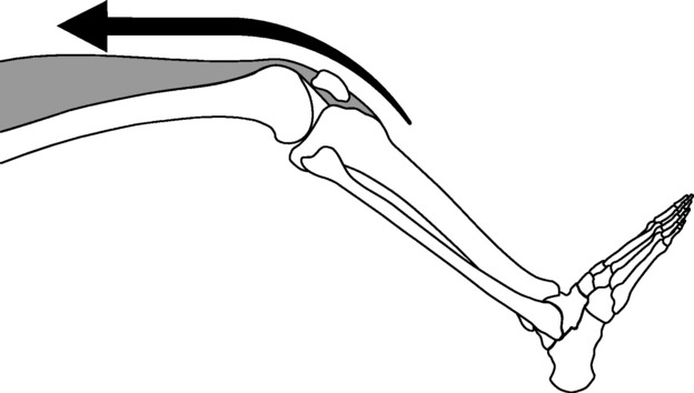
The quadriceps (Fig. 3.5) arise from the femur and act to extend the knee. The muscle faces a problem, however: if the knee is flexed, it has to somehow ‘get round the corner’. It achieves this by inserting into the superior pole of the patella, a large sesamoid bone that acts as a pulley, its reciprocally curved deep surface sliding between the two condyles of the femur. A tendon then runs from the inferior pole of the patella to the tibial tuberosity, so that contraction of the muscle will extend the knee: the quadriceps move the patella; the patella moves the tibia.
Moment of inertia
The direction of pull of a muscle – called its line of action – is an important consideration when considering the turning force created in a joint by a muscle. This turning effect is known as a moment of inertia (moment for short) and applied to any object that is able to rotate about an axis such as the forearm, which rotates about the elbow or, in the first instance, a door, which rotates about its hinge (Fig. 3.6).
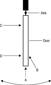
In Figure 3.6, we see four ways in which a force could be applied to the door and we know intuitively from our daily experience what will happen if we push the door in each of the instances A–D. Force A will not move the door as it is not generating a turning force, merely pushing the door into its hinges. Force C will move the door with all of the force directed in the right direction but we all know the door will move much more easily if we push further away from the hinge, exactly as is the case with a lever and its fulcrum, as is the instance with Forces B and D.

This is best understood by reconsidering the four examples on an individual basis. If we consider example C (Fig. 3.7) first, we do not need to resolve the vector of forces because all of the force is being directed at right angles to the door. The distance, s, from the line of action of the force (F = 10 N) is 20 cm; therefore, the moment is:
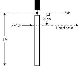
Figure 3.7 • A force of 10 N being applied at right angles to a 1 m door at a distance of 20 cm from the axis (hinge).

In example D (Fig. 3.8), the force is again acting perpendicularly to the door but this time the perpendicular distance from the line of action of the force to the axis of rotation is 80 cm.
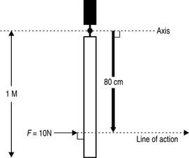
Figure 3.8 • A force of 10 N being applied at right angles to a 1 m door at a distance of 80 cm from the axis (hinge).

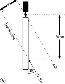
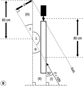
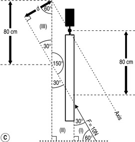
When we consider example C (Fig. 3.9), we have a more complex situation as the calculation of the perpendicular distance from the line of action of the force to the pivot now requires some consideration and a little bit of trigonometry. If we look at the situation in (A), we can see the distance that we need to calculate, d. In order to do this, we need to construct a short series of right-angled triangles so that we can use basic trigonometry to calculate the angles and lengths required.

In the final example, A (Fig. 3.6), the line of action is perpendicular to the axis; therefore, the distance is zero:
Example 1
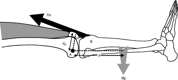
In Figure 3.10, the biceps brachialis muscle is holding the arm stationary against two forces, a 20 N weight held in the hand and the weight of the forearm itself, which is regarded as operating through its centre of gravity. We wish to know what force the muscle needs to generate in order to maintain this posture.
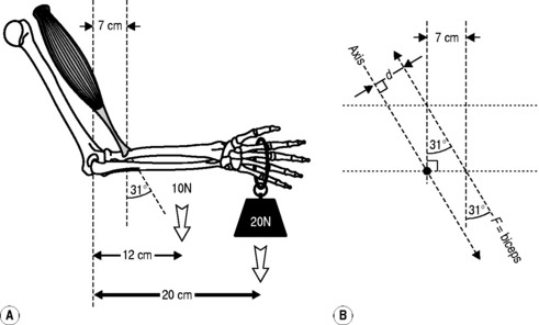

which can be written as:


As it is the force that we are trying to calculate, we can rearrange this as: