Diagnostic imaging

Chapter 9 Diagnostic imaging


Introduction


Since Röntgen first took the blurred, indistinct image of his wife’s hand at the end of the 19th century, diagnostic imaging has changed beyond all recognition. Patient (and practitioner) exposure has decreased, quite literally, by an order of magnitude; meanwhile, imaging quality has been enhanced to the point where it is now possible, using computed tomography, to produce three-dimensional colour films … where films are used at all; digitization means that most images are now read on computer screens. This means that they can be instantly magnified and exposure parameters modified as required.


Over the past 30 years, it has become possible to image not only bone but soft tissues as well, revolutionizing the diagnosis and management of injury and disease processes. These changes have, inevitably come at a price. Whereas a new x-ray machine can be purchased and installed for under $100 000, the cost of magnetic resonance imagers start at over $1 500 000 and positron emission tomography costs many times more. The recent development of ultrasound as an imaging modality has started to drag costs back and offer some relief to over-stretched medical budgets. However, as patient expectations and the population age profile both increase, clinicians are being forced into cost/benefit decisions unknown to the previous generation (though not to private manual therapists working with self-funding patients). They must also now become familiar with a raft of different imaging modalities based on a much wider array of underlying principles (i.e. physics) and understand how and why their patients would benefit from referral.


In some manual disciplines, practitioners might also be expected to competently interpret and clinically correlate advanced imaging findings – in both instances, without understanding the fundamentals behind how the images are generated, produced and recorded, the task becomes a feat of memory rather than the consequence of understanding.


This chapter begins with traditional, plain film x-ray in which the basic principles have remained largely unchanged since Victorian times. We will then consider the consequences of the arrival of silicon chip technology, which allowed sufficient computing power to assimilate data into multiple, sequential images, both from x-rays and from the behaviour of individual atomic nuclei within the body, which can be detected, recorded and accurately interpreted. The chapter concludes with consideration of a new application for old technology; ultrasound, which is now providing a cheap, portable, non-invasive alternative to evaluate both injury and illness.


The x-ray machine


We have already considered the basics of x-ray production in the previous chapter – take some electrons; accelerate them so that they have lots of energy; smash them into a piece of tungsten and, hey presto, x-rays!


It is now time to understand how those elements work in practice.


Thermionic emission


As we have already discovered, many metals have, at room temperature, a ‘sea’ of disassociated electrons within their lattice structure. These ‘free’ electrons can move around in response to an applied electromagnetic field; however, under normal conditions the negative charges on all these electrons are cancelled out by the positive charges on the atoms of the metal.


If the metal is heated, however, the electrons gain kinetic energy. Occasionally, one electron will gain so much energy that it is capable of overcoming the attraction of the nuclei and can fly off into the metal’s surroundings. When this happens, the electron-deficient metal develops a positive charge resulting in an electrostatic attraction between the (negatively charged) electrons that have leapt out of the metal and the (positively charged) metal they have left.


The result of this is the production of a space charge. The hot metal becomes surrounded by a ‘cloud’ of electrons that have jumped out of the metal before being drawn back by the attraction between the electron and the metal. We see this effect every time we switch on a conventional electric light bulb.


Taken overall, the system remains electrically neutral – sum the charges of electron cloud and metal at any moment, and the result will still be zero. This process of ‘boiling off’ electrons is known as thermionic emission.


In an x-ray machine, the thermionic filament is traditionally made from tungsten. This element is particularly useful in this context, not only because it is relatively inexpensive and easily available but because of its work function profile (Fig. 9.1) and its high melting point (3 683K). When the x-ray machine is switched on, the filament is heated only slightly by a current that is low enough that it is below the threshold for thermionic emission. It is further protected from too rapid heating by a thermistor, described in Chapter 8 as a device whose conductance increases with temperature.


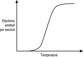
Once the filament current is high enough for thermionic emission to occur, we can see from Figure 9.1 that it takes only a very small increase in temperature (produced by the heating effect of the current) to effect a very large increase in the number of electrons produced. There is an upper limit to electron production. This is determined by the mutual repulsion between the electron cloud and the electrons within the filament that are trying to escape, the space charge effect. Beyond this point, very few further electrons are produced, regardless of how much additional current is introduced. The risk of vaporizing the tungsten also increases, thus limiting the effective filament current to below this level.


Electron production


Practical considerations mean that most commercial x-ray machines have filament currents that are in the range of 3–6A. The heating effect of this current is used to generate thermionic emission in the tungsten filament. It is important not to confuse the filament current with the tube current, which is the number of electrons per second travelling from the filament to the target, measured in mA. This is one of three defining factors for an x-ray exposure and is pre-set by the operator, usually in increments of 50 mA. For musculoskeletal radiography, this range will usually cover from 50 mA (for extremities) to 300 mA (for lumbopelvic views of obese patients).


Radiographers invariably refer to the tube current as the ‘mA’; however, by itself it does not tell us how many electrons are available for x-ray production, merely how many are being directed at the target per second.


This brings us to the second defining measure of a patient’s exposure, the length of time over which electrons are produced, which will mirror the length of time over which x-rays are produced and therefore the amount of exposure. The exposure time is measured in seconds although, in reality, it will usually be fractions of a second. These two factors are usually combined to reflect the number of electrons produced, the mAs, which again is referred to in terms of its units (‘em-ay-ess’).


Thus, an mAs of 100 can be produced by a filament current of 100 mA operating for one second or by a filament current of 200 mA operating for half a second or 250 mA for 0.4 s.


All these value combinations produce the same number of electrons. If we recall that an amp is a coulomb per second, then:


image


There are 1.6 × 10⁻¹⁹ C per electron, therefore there are:


image


Therefore, 100 mC has 6.25 × 10¹⁷ electrons.


Usually, the radiographer will be provided with a set of protocols with measurements related to the thickness of individual body parts. These protocols allow them to ascertain the optimum mAs for a patient of any size; they must then determine the best combination of tube current and exposure time; for example, if a cervical spine x-ray is taken at 16 mAs and the radiographer chooses to take it at 200 mA, then the exposure time will be:


image


Because the filament is producing negative electrons that are going to be accelerated towards the (positive) target, the filament is termed the cathode. It has one further component of which we should be aware, the focusing cup. The filament is housed within the focusing cup, which is negatively charged. Although this increases the space charge effect, this disadvantage is offset by the directionality it gives to the electron beam, which otherwise tends to rapidly spread out (owing to mutual repulsion) to the point where many electrons miss the target altogether.


imageCLINICAL FOCUS


No two patients are identical and the radiographer must consider a number of factors when determining the patient exposure. If a patient moves during the course of an exposure, the result is the same as it would be in conventional photography: the resulting image is blurred.


Unlike conventional photography, which is merely collecting reflected light, radiography involves significant doses of ionizing radiation passing through the patient before being collected on the film, which is placed behind them. Everything possible is therefore done to ensure a minimum number of repeated exposures.


As a rule, x-rays are taken at the fastest possible exposure time. This needs to be balanced against using the tube at unnecessarily high mA values, which shortens the tube life (generally, there is little to be gained by taking a 3 mAs radiograph of a foot using an exposure of 0.01 s/300 mA when 0.03 s at 100 mA is fast enough to preclude the possibility of any motion artifact).


There are considerations that may affect this decision. A patient with a parkinsonian tremor or other conditions of involuntary movement, may require a faster than usual exposure time to ‘freeze’ the joint being imaged.


Although in hospitals most x-rays are taken with the patient lying down, manual physicians want to elicit as much biomechanical information as possible from the resultant films and this often involves x-raying the patient standing up. They then have to overcome the difficulties posed by patients with antalgia, ataxia, balance and respiratory problems, as well as the higher doses often necessitated by upright films. This is particularly true of films of the lower spine (when a spinal film of an overweight patient is taken with the patient lying prone, the fat is pushed to the side by their own weight leaving less soft tissue to penetrate).


Electron energy


As we saw in the last chapter, when electrons interact with matter, there are a number of events that may occur. As we are only interested in the production of diagnostic quality x-rays, i.e. those capable of penetrating the patient and being detected once they have done so, we should be particularly keen to avoid electron interactions that produce heat and weak Bremsstrahlung radiation.


This involves having electrons with high energies, which means in turn that they must be accelerated to a high speed. This is done by sealing the filament and the tungsten target at which the electrons will be fired in a sealed glass cylinder containing a vacuum. This comprises the x-ray tube. The absence of air prevents the electrons interacting with the molecules of nitrogen, oxygen, carbon dioxide and trace elements, which would only produce low-energy x-rays (small nuclei, therefore lower electron shell binding energies) and limit the number and energy of those electrons reaching the target.


The electron energy comes from placing a high voltage across the two ends of the x-ray tube. We have already termed the filament the cathode; the other end of the potential gradient is the tungsten target, the anode. Electrons are repelled from the cathode and attracted to the anode, the higher the potential difference between the two, the greater the electrons’ energy when they strike the target.


In order to do this, a number of obstacles must be overcome. The first of these relates to the voltage supply to the room in which the x-ray is located. We have already seen how the nominal voltage can vary depending how far one is from the nearest substation. It can also vary from hour to hour and from one season to another depending on demand: a frost warning on the weather forecast can cause a sudden dip in power as millions of heaters and boilers are all turned on at once, before power stations can adapt to the increased demand.


Most x-ray machines operate on 220 V but this can easily vary by 5% or more, which does not help the production of consistent, high-quality x-ray beams. The problem is overcome by the insertion of a line compensator, which measures and monitors the incoming voltage and will automatically adjust the incoming voltage to be exactly 200 V at all times.


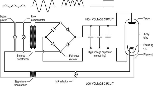
It does this by being wired to the next x-ray component, the autotransformer. Although this works on a subtly different principle from the transformers that we considered in Chapter 7, the underlying physics remains the same – a primary voltage induces a magnetic field in a shared ferromagnetic core. This, in turn, induces a secondary voltage. By adjusting the ratio of the number of coils around the core in the primary and secondary circuits, the secondary voltage can be increased or decreased compared to the primary.


In a typical x-ray machine, the transformer steps up the voltage by a factor of 500 to produce voltages of up to 110 kV across the length of the tube. This secondary voltage is referred to in terms of ‘kilovolts peak’ (kVp) and, once again is referred to in terms of its units (‘kay-vee-pee’), the third and last of the factors determining exposure.


Although there are now plenty of available electrons and the means to impart significant amount of energy to them, there remains one further obstacle. The mains supply to the x-ray machine, whether single phase or multi-phase, is in the form of alternating current. This means that 50 or 60 times per second, it fluctuates from positive to zero to negative and back to zero. This means that the electrons are bounced up and down the x-ray tube and spend at least half their time travelling in the wrong direction.


The solution is, of course, to include a rectifier in the circuit immediately after the transformer (remember, direct current cannot be transformed). As it would be unproductive to have the tube sitting idle for half the time, full wave rectification is used, and this ensures that the filament end of the tube is always negative and the target always positive.


High-voltage capacitors are then used to smooth the circuit to deliver a constant, controllable, high voltage across the vacuum between cathode and anode (Fig. 9.2).


Production of x-rays


There are a number of considerations that must be made regarding the x-ray target before electrons are haphazardly smashed into it. The first is the choice of material. Why tungsten? The element scores highly on a number of essential characteristics. In addition to being relatively cheap and easily available, tungsten has a high atomic number. This means a high K-shell binding energy and, therefore, a greater number of high-energy (and, thus, diagnostic) x-rays. It also has a high liquefaction point – almost three times that of copper – which means that it can withstand high tube current without melting, pitting or vaporizing (a common cause of tube failure). Finally, tungsten has good thermal conductivity. It is therefore efficient at dissipating the heat away from the immediate area of electron contact.


Although in dental x-ray machines, the low exposures mean that a fixed target can be used, in medical machines, capable of imaging a pelvis, if the electron beam were always centred on a single spot, that area would soon become damaged and degraded and the (expensive) tube, ruined.


One way around this problem is to rotate the target, thus spreading the area of electron bombardment around the whole of the circumference of the circular target. This can increase the potential target area from just 5 mm2 to more than 1500 mm2. Typically, x-ray targets rotate at speeds of 50 revolutions per second.


Heel effect


The x-ray target must also be carefully shaped (Fig. 9.3A) in order to direct as many of the x-rays as possible towards the target (patient) rather than randomly, in which event they will be absorbed by the protective lead casing of the tube rather than used for their intended purpose. The edge of the rotating anode is bevelled – usually at an angle of about 6° – in order to direct the x-rays towards the aperture, the hole through which the radiation is directed at the patient. Metal sliding panels called collimators can cover all or part of the aperture to further limit the spread of the beam and to ensure that only the targeted area is exposed.


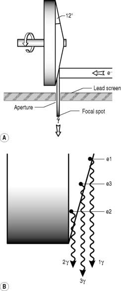
Unfortunately, for every innovation there is a consequence, and the sloping of the target means that the x-rays that are produced have varying amounts of tungsten to penetrate before emerging from the target and therefore a higher chance of interacting with other tungsten atoms before emerging. This means that the x-ray beam that emerges from the aperture will be more intense on the cathode side than the anode side, the heel of the target (Fig. 9.3B). This will have an effect on the x-ray penetration of the patient and the final image, which can be under-exposed on one side and over-exposed on the other.


Quantity of x-rays


The intensity of an x-ray beam is most commonly measured in roentgens (R), even though this is not an official SI unit. A typical diagnostic x-ray exposure produces x-ray intensities of 5 mR per mAs giving a variation from 15 mR for a hand x-ray to 1.2 R for a lumbar spine lateral view.


A number of factors can affect the quantity of x-rays reaching the patient. We have already discussed mAs, which is directly proportional to the quantity of x-rays (if the mAs is increased, the number of electrons hitting the target increases as does the number of x-rays produced).


The relationship between x-ray quantity and kVp is slightly more complicated. If the kVp is altered, then the ratio of the new x-ray beam intensity to the previous beam is proportional to the square of the ratio of the change in kVp. This is best understood by looking at a couple of examples. If the kVp is increased from 70 to 90, the intensity of the x-ray beam will increase by:


image


This is the ratio by which the beam intensity increases; that is, a 29% increase in tube voltage, will give an increase of 65% in the number of x-rays produced. In a similar vein, if the kVp is reduced from 100 to 92, the x-ray intensity will decrease to:


image


Therefore, an 8% decrease in kVp will create a 15% drop-off in x-ray intensity. The relationship to image is even more complicated because, at higher kVp values, the x-rays have more energy and so more will penetrate the patient to reach the film and expose it.


The final consideration when determining the number of x-ray photons reaching the patient is that of source-image distance (SID), yet again referred to by its acronym (‘ess-eye-dee’). The x-ray beam spreads out as it travels from the point source of the tube aperture and the manner in which it does this is governed by the inverse square law.


Typically, diagnostic x-rays are taken at distances of between 90 cm and 150 cm; the distance is often fixed to remove the necessity of allowing for yet another variable when determining the x-ray factors for a given patient’s exposure. However, it is quite easy to appreciate that if the SID is doubled, the mAs must be increased by a factor of four; if tripled, by a factor of nine.


Quality of x-ray


The quality of an x-ray beam is referred to in terms of its penetrability, that is, its ability to permeate matter: the higher the quality of the x-rays, the higher the penetrability. This can be quantified by using the attenuation of the x-ray beam.


You will recall from the last chapter that x-rays are attenuated exponentially; that is, if 50% of x-rays of a given energy are stopped by 1 cm of a given material, then 75% (i.e., half the remaining x-rays) will be stopped by 2 cm, 87.5% by 3 cm and so on. The amount of material required to reduce the beam by 50% is known as the half-value layer (HVL) of the material.


Unfortunately, this mathematical relationship breaks down when considering a diagnostic x-ray beam, which is not homogeneous but consists of x-rays of a wide range of energies. The situation is further complicated by the fact that the patient is also non-homogeneous; bone has a different HVL to blood or fat or muscle. The HVL characteristic of an individual x-ray machine is therefore determined by experiment rather than calculation, using (homogeneous) aluminium filters. A diagnostic x-ray beam usually has a HVL of approximately 4 mm for aluminium, which is around half that of the average soft tissue matrix of the patient.


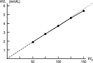
There are, once again, several factors that can affect the quality of x-rays. Before discussing these, it is worth noting that neither mAs nor SID have any effect on the quality of the beam, only the quantity of x-rays produced. kVp does affect the quality, as might be expected. Increasing the energy of the electrons hitting the target results in the production of more high-energy x-rays, which means the spectrum of x-ray energies is shifted to the right and more high-energy characteristic x-rays will be produced. There is no direct linear relationship between kVp and HVL; however it is approximately proportional (Fig. 9.4).


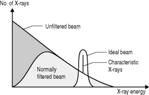
As is implicit from the discussion of HVL, filtration can also affect the quality of the beam. If a filter is placed between the x-ray source and the target then a greater proportion of low-energy x-rays will be attenuated than high-energy x-rays. Although this will reduce the quantity of x-rays reaching the patient, it will increase their quality. The most commonly selected material for x-ray filters is aluminium; it is cheap and, because of its relatively low atomic number (Z = 13), allows through a relatively high proportion of high-energy x-rays but will stop low-energy x-rays through the photoelectric effect.


The thicker the filter, the more photons are stopped and the higher the energy profile of the photons remaining in the emergent beam; however, practical considerations limit the thickness of filters – if the quantity of x-rays is diminished too much, not enough photons reach the patient to obtain a diagnostic image within a realistic timeframe.


There are two types of filter employed in the x-ray room. Inherent filtration is included in the x-ray tube as is a combination of the glass screen over the aperture and added aluminium, usually a thin sheet placed between the target and aperture to remove as many low-energy x-rays as possible without significantly affecting the quantity of photons. As this filtration is fixed, its effects can be incorporated in the exposure protocols for a given machine. The effects of this collimation are shown in Figure 9.5.


Compensating filters are also employed by the radiographer. These are often wedge-shaped and are used to gradate a beam. For a body part that is, itself, wedge shaped, such as the thoracic spine or foot, the filter (which is placed over the emergent beam) is aligned so that the thickest part of the filter is over the thinnest part of the anatomy.


The factors that affect x-ray quality and quantity are summarized in Table 9.1.


Table 9.1 Factors that affect the quality and quantity of x-rays


Factor Effect upon
X-ray quantity X-ray quality
mAs Increases in direct proportion None
SID Decrease according to inverse square ratio None
kVp Increases in proportion to the square of the ratio of the increase Increases approximately proportional
Filtration Decreases exponentially Increases


Patient exposure


In Chapter 8, we examined the ways in which x-rays can interact with matter. In diagnostic radiography, only two of these are important: the Compton and photoelectric effects. They are, however, only important in a negative sense – it is the x-rays that pass through the patient without undergoing any interaction with matter that form the image of the patient in which we are interested.


It is the photoelectric effect that gives us the image of the patient; if all x-rays were to pass through the patient, the resultant image would be uniformly dark or radiolucent. If all the x-rays were to be absorbed, the image would be uniformly white or radio-opaque. It is the fact that x-rays are differentially absorbed in the photoelectric effect that is important to the clinician.


You will recall that the chance of the photoelectric effect occurring was inversely proportional to the cube of the x-ray’s energy and to the cube of the atomic number of a given atom. Differential absorption therefore increases as the kVp is decreased; however, if it is decreased by too much, not enough x-rays will pass through the patient to form a diagnostic image.


The effective atomic number of different soft tissues is dependent on the relative proportion of atoms within their matrix. Bone, for example, is made from hydroxyapatite, which contains calcium (Z = 20) and phosphorus (Z = 15). It has an effective atomic number of 13.8. By contrast fat, which is principally composed of hydrogen (Z = 1) and carbon (Z = 6), has an effective atomic number of 6.3 (other soft tissues average 7.4).


Therefore, photoelectric absorption is:


image


The chance of interactions is also related to the mass density of the material — bone is denser than fat and therefore there are more atoms with which the x-rays can interact. So, the probability of x-ray interactions (of either type) is directly proportional to the mass density of the material (Table 9.2). This is why interaction is much more likely in lung tissue than in air, despite the fact that their effective atomic numbers are almost identical. The actual chances of either Compton scattering or the photoelectric effect occurring in lung tissue is:


Table 9.2 Effective atomic number and mass densities of different body materials


Tissue type Effective Z Mass density (kg m−3)
Bone 13.8 1850
Muscle 7.4 1000
Fat 6.3 910
Lung 7.4 320
Air 7.6 1.3


image


This also means that the photoelectric effect is not 8.3 times more likely to occur in bone that fat because we have not considered the contribution mass density will make to the chances of interaction:


image


Therefore, the chances of the photoelectric effect occurring in bone are actually:


image


Therefore, bones are very much more radio-opaque than fat, which is why they appear white on x-ray images and the surrounding soft tissues are darker.


By contrast, Compton scattering – the alteration in direction of an incident photon after an interaction with an outer-shell electron – contributes nothing to the diagnostic quality of the image; rather, it detracts from it. Scattered x-ray photons create film fogging, degradation of the diagnostic image by photons that do not relate to the absorption or transmission by body parts. A Compton scattered photon might land anywhere on the receptor (or, indeed, miss it altogether) and detract from the optical contrast.


The Compton effect is independent of atomic number but is directly proportional to the mass density; the Compton effect also increases with increasing kVp.


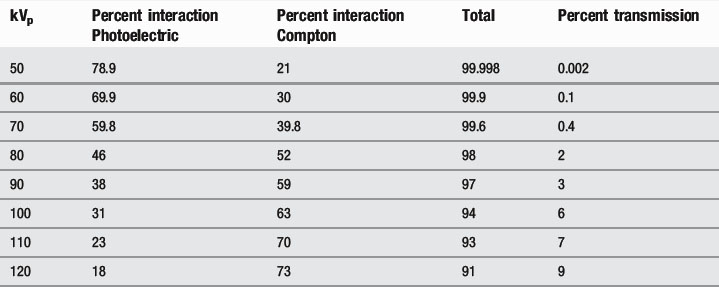
This means that, at lower kVp values, the photoelectric effect dominates, whilst, at higher values, the Compton effect is more important. Increasing the kVp also increases the percentage of x-rays that pass through the patient (Table 9.3).


Stay updated, free articles. Join our Telegram channel

Apr 4, 2017 | Posted by in GENERAL & FAMILY MEDICINE | Comments Off on Diagnostic imaging

Full access? Get Clinical Tree

Get Clinical Tree app for offline access