(3.1)
where f is the average Tresca friction coefficient for a hot working process: its value ranges from 0 (perfect sliding) to 1 (sticking friction). R th and H are the radius of the sample in the absence of bulging (or condition without friction) and final height of the sample, respectively. The barreling factor, b, is given by the following equation:
(3.2)
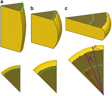
Fig. 3.1
The shape of the cylindrical sample at true strain levels of (a) 0.3, (b) 0.65, and (c) 1.5 at friction coefficient of 0.5 simulated by DEFORM-3D software (Reprinted from Ref. [41], with kind permission from Springer Science + Business Media)
In this study, using the DEFORM-3D FEM software, we simulated the evolution behavior of various parameters of a cylindrical sample such as R t, R c, and R m in hot compression processes by adjusting the average Tresca friction coefficient f. On the basis of the results of simulation, the identification of f was carefully established just by analyzing the abovementioned nondimensional parameters [41]. We simulated the shape of the sample by means of the DEFORM-3D FEM software for various values of f: in this case, f was considered to be constant or, in other words, independent of strain in each compression process. For f = 0.5, the simulated shapes of the sample at true strains of 0.3, 0.65, and 1.5 are shown in Fig. 3.1a, b, and c, respectively. When the true strain was 0.3, it was observed that the contact surface of the compressed cylindrical sample was formed mainly by the original flat end surface of the sample after broadening; in this case, R t was approximately equal to the radius of the deformed contact surface of the sample with the anvil (Fig. 3.1a). However, at strain levels of both 0.65 and 1.5, the contact surface consists of both the original flat end surface (characterized by the dashed line) and the annular surface due to the contact of the lateral surface of sample after barreling.
From the simulation results, R t, R m, and R c as a function of friction coefficient at different strain levels can be calculated, on the basis of which new relationships between the parameters R t, R m, original geometrical parameter of the sample (H 0, R 0), and the friction coefficient f could be established [41]. When considering the relationship between f and the geometry of the sample, since there are similar trends between R c and R m from the simulation results, we just considered R m in this study and combined it with other parameters such as the sample height after compression, H, R t, and the initial height of the sample H 0 into R m H/R t H 0 for each process as a function of the true strain level, respectively. The plots show gradual decreases in the values with an increasing strain level at each compression process. Let 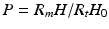 ; therefore, the relationship between true strain and P in each compression process can be exactly expressed by a spline equation as follows:

where A, B, and C are variables and
These parameters are constants and independent of materials or experimental condition as given in Table 3.1. By inserting Eqs. 3.4, 3.5, and 3.6 into Eq. 3.3, the relationship between f and P can be summarized as

where P is able to be obtained easily by measuring the geometry of the deformed sample and other parameters in this equation are available in Table 3.1 in the case of the current sample.
; therefore, the relationship between true strain and P in each compression process can be exactly expressed by a spline equation as follows:(3.3)
(3.4)
(3.5)
(3.6)
(3.7)
On the basis of Eq. 3.7, the relationship among the nominal strain, parameter P, and friction coefficient f is plotted in Fig. 3.2 by a contour map; the relationship between these parameters could be observed clearly. For a deformed sample, parameter P and nominal strain could be easily obtained; in this case, f could be read directly from this figure [41]. For example, if a cylindrical sample was compressed to a nominal strain of 0.5 (50 %) and the geometrical parameter P was calculated to be about 0.68, then the friction coefficient f should be about 0.45 as shown in Fig. 3.2.
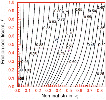
Fig. 3.2
Relationships among nominal strain, friction coefficient f, and parameter P in cylindrical compression tests (Reprinted from Ref. [41], with kind permission from Springer Science + Business Media)
3.2.2 Friction Correction
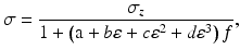
Rowe analyzed the influence of interfacial friction between a workpiece and a tool [42] and found that, without the influence of friction for a circular disk, the relationship between the average axial pressure and stress is
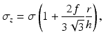
where r and h are the instantaneous radius and height, respectively, of the sample and σ and σ z are the equivalent axial stresses without and with frictional conditions, respectively. Dieter also proposed a Coulomb stress distribution at both end surfaces of the cylindrical sample [43] and found that the average axial stress (mean height of the friction hill) with respect to the stress without friction is
![$$ \sigma =\frac{{C_f}^2{\sigma}_z}{2\left[ \exp \left({C}_f\right)-{C}_f-1\right]}, $$](/wp-content/uploads/2016/10/A335203_1_En_3_Chapter_Equ9.gif)
where

In the above equation, μ denotes the Coulomb friction coefficient. The relationship between the Tresca friction coefficient f and the Coulomb friction coefficient μ is

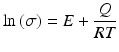
It should be noted that Eqs. 3.8 and 3.9 are based on the assumption that there is no barreling at the edges of the sample and that the thickness is small enough so that the average axial stress σ z/σ may be taken as constant throughout the sample thickness. However, in an actual cylindrical hot working process, the sample thickness is generally greater than its radius. In addition, the stress is considered to vary greatly as a function of the sample height. Therefore, these two theories are not applicable to an actual compressive test. A more precise equation for compensating the stress–strain curve is therefore required for a cylindrical compression test because the stress distributions both within the sample and at the interface between the sample and the anvil vary with the height/radius ratio and with the friction condition.
(3.8)
(3.9)
(3.10)
(3.11)
In the current study, we used the DEFORM-3D FEM software to simulate the evolutionary behavior of flow stress in a sample under compression by adjusting the average Tresca friction coefficient f. To analyze the variation of flow stress with respect to the initial height/diameter ratio of the sample, a series of simulations were performed for samples with various initial heights (same diameter). In this chapter, we propose a pragmatic and simple approach to compensate the stress–strain curve.
Models of the aforementioned samples were generated using DEFORM-3D v6.13. To reduce the calculation time, one-eighth of the cylindrical sample with a mesh number of 30,000 was considered in the FEM model for analysis. The values of the Tresca friction coefficients f selected for each simulation were 0 for perfect sliding and 0.1–1, in increments of 0.1, for restriction condition between the sample top surfaces and the anvils. FEM analysis was carried out to a true strain of about 1.8 (nominal strain of approximately 85 %) [44].
The simulated compression processes were performed using a true strain rate-controlling process of 10−3 s−1. In addition, the heat efficiency was chosen to be 0 in the simulation process so that adiabatic heating (temperature rise) would not occur inside the compressed sample (it leads to softening of the flow stress in the deformation process). All of the above settings for the simulation process are based on the fact that the compensation of stress both from adiabatic heating and from the stroke rate effect can be performed independently, as we mentioned above [44].
Let the dimensionless parameters σ z and σ represent the stress with and without the influence of friction, respectively, during the compression process. Therefore, the ratio σz/σ is a parameter expressing the extent to which friction influences the stress of materials. For a sample with Rastegaev geometry, the influence of friction on the flow stress of materials is very small for strain values less than approximately 0.6; however, at high strain levels, the stress increases sharply because of the friction. Oh et al. [45] studied the cylindrical compression of a Ti alloy sample with Rastegaev geometry to a true strain level of approximately 0.6–0.7 using DEFORM-3D FEM software, and their findings suggest that stress variations due to the influence of friction are below 5 % for strain values below 0.6–0.7, which is in good agreement with the current results. However, they did not report any results for higher strain levels. The results of our current study indicate that, at a high strain level, the influence of friction is extremely large. In fact, numerous compression tests were conducted using a high strain level to further refine the microstructure or improve the mechanical properties of the final products. Therefore, analyzing the influence of friction at both high and low strain levels is important. From the plot of σ z/σ as a function of average Tresca friction coefficient f at different strain levels, we find that f is linear to σ z/σ, where the slopes K of these lines are closely related to the nominal strain levels. From the abovementioned results and for a specific strain level, the relationship between the ratio σ z/σ and f is [44]
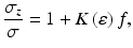
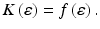
where the slope K(ε) of the line depends on the strain
The plot of the slope K(ε) can be calculated as a function of the true strain. We find that the curve can be expressed by a third-order spline equation:
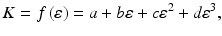
where a, b, c, and d are constants determined by the fitting process and their suitable values are listed in Table 3.1. By substituting Eq. 3.14 into Eq. 3.11, correcting the stress–strain curve for a sample with Rastegaev geometry is obtained:
where f can be calculated using the methodology developed in the previous section. The stress without the influence of friction can be compensated by inserting the other parameters of Table 3.1 into Eq. 3.14, regardless of the experimental conditions or of the characteristics of the material.
(3.12)
(3.13)
(3.14)
(3.15)
3.3 Adiabatic Correction
It has been reported that over 90 % of the input energy during high-speed deformation is converted into heat due to adiabatic heating. This results in the softening of flow stress and its decreases as compared to the ideal isothermal deformation conditions [46, 47]. The temperature rise due to adiabatic heating during deformation is usually calculated by [46, 47]
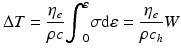
where ΔT is the temperature rise due to the work done on the sample, ρ is the density of the sample, and c h is the heat capacity of the material;  is the heat efficiency and is empirically dependent on the strain rate as [48]
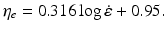
From Eq. 3.17, the temperature rise and the subsequent softening are usually more significant at high strain rates due to the short dissipation time and high input energy. At a certain strain rate and strain level, the flow stress after adiabatic correction can be calculated from
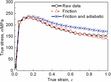
where  . An example of deformation curve biomedical Co–29Cr–6Mo–0.12C–0.16 N alloy (T = 1150 °C, strain rate = 1 s−1) after corrections of both friction and adiabatic heating is shown in Fig. 3.3; in this case, the friction coefficient was calculated to be 0.52, and it can be seen that the influence of friction on the deformation curve is not so significant below the true strain level of 0.6, while the effect of adiabatic heating on deformation curves has a much influence on the entire shape of deformation curves.
(3.16)
is the heat efficiency and is empirically dependent on the strain rate as [48](3.17)
(3.18)
. An example of deformation curve biomedical Co–29Cr–6Mo–0.12C–0.16 N alloy (T = 1150 °C, strain rate = 1 s−1) after corrections of both friction and adiabatic heating is shown in Fig. 3.3; in this case, the friction coefficient was calculated to be 0.52, and it can be seen that the influence of friction on the deformation curve is not so significant below the true strain level of 0.6, while the effect of adiabatic heating on deformation curves has a much influence on the entire shape of deformation curves.