Rheology
Christopher Marriott
Chapter contents
Viscosity, rheology and the flow of fluids
Viscosity coefficients for Newtonian fluids
Laminar, transitional and turbulent flow
Determination of the flow properties of simple fluids
Types of non-Newtonian behaviour
Determination of the flow properties of non-Newtonian fluids
The application of rheology in pharmaceutical formulation
Key points
Viscosity, rheology and the flow of fluids
The viscosity of a fluid may be described simply as its resistance to flow or movement. Thus water, which is easier to stir than syrup, is said to have the lower viscosity. The reciprocal of viscosity is fluidity. Rheology (a term invented by Bingham and formally adopted in 1929) may be defined as the study of the flow and deformation properties of matter.
Historically the importance of rheology in pharmacy was merely as a means of characterizing and classifying fluids and semi-solids. For example, all pharmacopoeias have included a viscosity standard to control substances such as liquid paraffin. However, the increased reliance on in vitro testing of dosage forms as a means of evaluating their suitability for the grant of a marketing authorization and the increased use of polymers in formulations and the construction of devices has given added importance to measurement of flow properties. Furthermore, advances in the methods of evaluation of the viscoelastic properties of semi-solid materials has increased not only the amount and quality of the information that can be gathered but has also accelerated the time taken for its acquisition.
A proper understanding of the rheological properties of pharmaceutical materials is essential to the preparation, development, evaluation and performance of pharmaceutical dosage forms. This chapter describes rheological behaviour and techniques of measurement and will form a basis for the applied studies described in later chapters.
Newtonian fluids
Viscosity coefficients for Newtonian fluids
Dynamic viscosity
The definition of viscosity was put on a quantitative basis by Newton. He was the first to realize that the rate of flow (γ) was directly related to the applied stress (σ): the constant of proportionality is the coefficient of dynamic viscosity (η), more usually referred to simply as the viscosity. Simple fluids which obey this relationship are referred to as Newtonian fluids and those which do not are known as non-Newtonian.
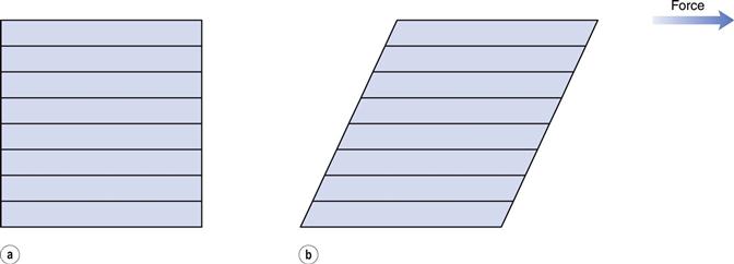
The phenomenon of viscosity is best understood by a consideration of a hypothetical cube of fluid made up of infinitely thin layers (laminae) which are able to slide over one another like playing cards in a pack or deck (Fig. 6.1a). When a tangential force is applied to the uppermost layer, it is assumed that each subsequent layer will move at progressively decreasing velocity and that the bottom layer will be stationary (Fig. 6.1b). A velocity gradient will therefore exist and this will be equal to the velocity of the upper layer in m s−1 divided by the height of the cube in metres. The resultant gradient, which is effectively the rate of flow but is usually referred to as the rate of shear, γ, will have units of reciprocal seconds (s−1). The applied stress, known as the shear stress, σ, is derived by dividing the applied force by the area of the upper layer and will thus have units of N m−2.
As Newton’s Law can be expressed as:
 (6.1)
(6.1)
then
 (6.2)
(6.2)
and η will have units of N m−2s. Thus, by reference to Equation 6.1, it can be seen that a Newtonian fluid of viscosity 1 N m−2s would produce a velocity of 1 m s−1 for a cube of 1 m dimensions with an applied force of 1 N. Because the derived unit of force per unit area in the SI system is the pascal (Pa), viscosity should be referred to in Pa s or mPa s (the dynamic viscosity of water is approximately 1 mPa s). The centipoise (cP) and poise (1 P = 1 dyn cm−2s) were units of viscosity in the now redundant cgs system. These are no longer official and therefore are not recommended but are still relatively commonly used.
The values of the viscosity of water and some examples of other fluids of pharmaceutical interest are given in Table 6.1. Since viscosity is inversely related to temperature, in this case the values given are those measured at 20 °C.
Table 6.1
Viscosities of some fluids of pharmaceutical interest
| Fluid | Dynamic viscosity at 20 °C (mPa s) |
| Chloroform | 0.58 |
| Water | 1.002 |
| Ethanol | 1.20 |
| Fractionated coconut oil | 30.0 |
| Glyceryl trinitrate | 36.0 |
| Propylene glycol | 58.1 |
| Soya bean oil | 69.3 |
| Rape oil | 163 |
| Glycerol | 1490 |
Kinematic viscosity
The dynamic viscosity is not the only coefficient that can be used to characterize a fluid. The kinematic viscosity (ν) is also used and may be defined as the dynamic viscosity divided by the density of the fluid (ρ):
 (6.3)
(6.3)
and the SI units will be m2 s−1 or, more usefully, mm2 s−1. The cgs unit was the Stoke (S = 10−4 m2 s-1) which together with the centiStoke (cS) may still be found in the literature.
Relative and specific viscosities
The viscosity ratio or relative viscosity (ηr) of a solution is the ratio of the viscosity of the solution to the viscosity of its solvent (ηo):
 (6.4)
(6.4)
and the specific viscosity (ηsp) is given by:
 (6.5)
(6.5)
In these calculations the solvent can be of any nature, although in pharmaceutical products it is most usually water.
For a colloidal dispersion, the equation derived by Einstein may be used.
 (6.6)
(6.6)
where ϕ is the volume fraction of the colloidal phase (the volume of the dispersed phase divided by the total volume of the dispersion). The Einstein equation may be rewritten as:
 (6.7)
(6.7)
when from Equation 6.4 it can be seen that as the left-hand side of Equation 6.7 is equal to the relative viscosity it can be rewritten as:
 (6.8)
(6.8)
where the left-hand side equals the specific viscosity. Equation 6.8 can be rearranged to produce:
 (6.9)
(6.9)
and as the volume fraction will be directly related to concentration, C, Equation 6.9 can be rewritten as:
 (6.10)
where k is a constant.
When the dispersed phase is a high molecular mass polymer then a colloidal solution will result and, provided moderate concentrations are used, Equation 6.10 can be expressed as a power series:
 (6.11)
Intrinsic viscosity
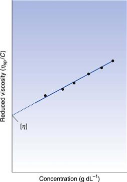
If ηsp/C, the viscosity number or reduced viscosity, is determined at a range of polymer concentrations (g dL−1) and plotted as a function of concentration (Fig. 6.2), a linear relationship should be obtained. The intercept produced on extrapolation of the line to the ordinate will yield the constant k1 which is referred to as the limiting viscosity number or the intrinsic viscosity, [η].
The limiting viscosity number may be used to determine the approximate molecular mass (M) of polymers using the Mark–Houwink equation:
 (6.12)
where K and α are constants that must be obtained at a given temperature for the specific polymer–solvent system using other techniques such as osmometry or light scattering. However, once these constants have been determined, then viscosity measurements provide a quick and precise method of molecular mass determination of pharmaceutical polymers such as dextrans, which are used as plasma extenders. Also, the values of the two constants provide an indication of the shape of the molecule in solution: spherical molecules yield values of α = 0, whereas extended rods have values greater than 1.0. A randomly coiled molecule will yield an intermediate value (≈0.5).
The specific viscosity may be used in the following equation to determine the volume of a molecule in solution:
 (6.13)
where C is concentration, N is Avogadro’s number, V is the hydrodynamic volume of each molecule and M is the molecular mass. However, it does suffer from the obvious disadvantage that the assumption is made that all polymeric molecules form spheres in solution.
Huggins’ constant
Finally, the constant k2 in Equation 6.11 is referred to as Huggins’ constant and is equal to the slope of the plot shown in Figure 6.2. Its value gives an indication of the interaction between the polymer molecule and the solvent, such that a positive slope is produced for a polymer that interacts weakly with the solvent, and the slope becomes less positive as the interaction increases. A change in the value of Huggins’ constant can be used to evaluate the interaction of drug molecules in solution with polymers.
Boundary layers
From Figure 6.1 it can be seen that the rate of flow of a fluid over an even surface will be dependent upon the distance from that surface. The velocity, which will be almost zero at the surface, increases with increasing distance from the surface until the bulk of the fluid is reached and the velocity becomes constant. The region over which differences in velocity are observed is referred to as the boundary layer which arises because the intermolecular forces between the liquid molecules and those of the surface result in a reduction of movement of the layer adjacent to the wall to zero. Its depth is dependent upon the viscosity of the fluid and the rate of flow in the bulk fluid. High viscosity and a low flow rate would result in a thick boundary layer, which will become thinner as either the viscosity falls or the flow rate is increased. The boundary layer represents an important barrier to heat and mass transfer.
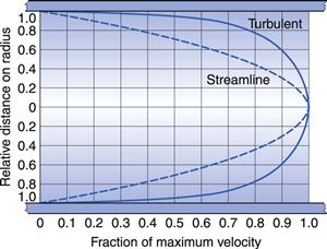
In the case of a capillary tube then the two boundary layers meet at the centre of the tube, such that the velocity distribution is parabolic (Fig. 6.3). With an increase in either the diameter of the tube or the fluid velocity, the proximity of the two boundary layers is reduced and the velocity profile becomes flattened at the centre (Fig. 6.3).
Laminar, transitional and turbulent flow
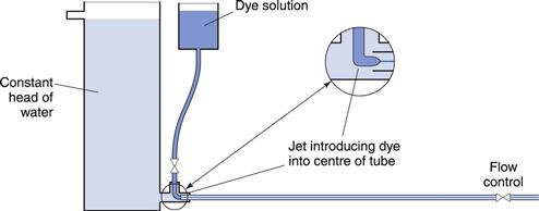
The conditions under which a fluid flows through a pipe, for example, can markedly affect the character of the flow. The type of flow that occurs can be best understood by reference to experiments conducted in 1883 by Reynolds who used an apparatus (Fig. 6.4) which consisted of a horizontal, straight glass tube through which the fluid flowed under the influence of a force provided by a constant head of water. At the centre of the inlet of the tube, a fine stream of dye was introduced. At low flow rates the dye formed a coherent thread which remained undisturbed in the centre of the tube and grew very little in thickness along the length. This type of flow is described as streamlined or laminar flow, and the liquid is considered to flow as a series of concentric cylinders in a manner analogous to an extending telescope.
If the speed of the fluid is increased, a critical velocity is reached at which the thread begins to waver and then to break up, although no mixing occurs. This is known as transitional flow. When the velocity is increased to higher values the dye instantaneously mixes with the fluid in the tube, as all order is lost and irregular motions are imposed on the overall movement of the fluid: such flow is described as turbulent flow. In this type of flow, the movement of molecules is totally haphazard, although the average movement will be in the direction of flow.
Reynolds’ experiments indicated that the flow conditions were affected by four factors, namely, the diameter of the pipe and the viscosity, density and velocity of the fluid. Furthermore, it was shown that these factors could be combined to give the following equation:
 (6.14)
where ρ is the density, u is the velocity, η is the dynamic viscosity of the fluid and d is the diameter of the circular cross-section of the pipe. Re is known as Reynolds’ number and, provided compatible units are used, it will be dimensionless.
Values of Reynolds’ number in a circular cross-section pipe have been determined that can be associated with a particular type of flow. If it is below 2000, then streamlined (i.e. to streamlined) flow will occur, but if it is above 4000, then flow will be turbulent. In between these two values the nature of the flow will depend upon the surface over which the fluid is flowing. For example, if the surface is smooth then streamlined flow may not be disturbed and may exist at values of Reynolds’ number above 2000. However, if the surface is rough or the channel tortuous then flow may well be turbulent at values below 4000, and even as low as 2000. Consequently, although it is tempting to state that values of Reynolds’ number between 2000 and 4000 are indicative of transitional flow, such a statement would only be correct for a specific set of conditions. This also explains why it is difficult to demonstrate transitional flow practically.
Nevertheless, Reynolds’ number is still an important parameter and can be used to predict the type of flow that will occur in a particular situation. The reason why it is important to know the type of flow which is occurring is that whereas with streamlined flow there is no component at right angles to the direction of flow, so that fluid cannot move across the tube, this component is strong for turbulent flow and interchange across the tube is rapid. Thus in the latter case, for example, mass will be rapidly transported, whereas in streamlined flow the fluid layers will act as a barrier to such transfer which can only occur by molecular diffusion.
Determination of the flow properties of simple fluids
A wide range of instruments exists that can be used to determine the flow properties of Newtonian fluids. However, only some of these are capable of providing data that can be used to calculate viscosities in fundamental units. The design of many instruments precludes the calculation of absolute viscosities as they are capable of providing data only in terms of empirical units.
Not all the available types of instrument used to measure viscosity will be described in this Chapter but it will be limited to simple instruments specified in various official pharmacopoeias.
Capillary viscometers
A capillary viscometer can be used to determine viscosity provided that the fluid is Newtonian and the flow is streamlined. The rate of flow of the fluid through the capillary is measured under the influence of gravity or an externally applied pressure.
Ostwald U-tube viscometer.
Such instruments are described in pharmacopoeias and are the subject of a specification of the International Organization for Standardization (ISO). A range of capillary bores is available and an appropriate one should be selected so that a flow time for the fluid of approximately 200 seconds is obtained; the wider-bore viscometers are thus for use with fluids of higher viscosity. For fluids where there is a viscosity specification in a pharmacopeia, the size of instrument that must be used in the determination of their viscosity is stated.
The viscometer is shown in Figure 6.5 and liquid is introduced through arm V up to mark G using a pipette long enough to prevent wetting the sides of the tube. The viscometer is then clamped vertically in a constant-temperature water bath and allowed to reach the required temperature. The level of the liquid is adjusted and is then blown or sucked into tube W until the meniscus is just above mark E. The time for the meniscus to fall between marks E and F is then recorded. Determinations should be repeated until three readings all within 0.5 seconds are obtained. Care should be taken not to introduce air bubbles and that the capillary does not become partially occluded with small particles.
The maximum shear rate, γm, is given by:
 (6.15)
where ρ is the density of the fluid, g the acceleration due to gravity, rc the radius of the capillary and η the absolute viscosity. Consequently, for a fluid of viscosity 1 mPa s, the maximum shear rate is approximately 2 × 10³ s−1 if the capillary has a diameter of 0.64 mm, but it will be of the order of 102 s−1 for a fluid with a viscosity of 1490 mPa s if the capillary has a diameter of 2.74 mm.
Suspended-level viscometer.
This instrument is a modification of the U-tube viscometer which avoids the need to fill the instrument with a precise volume of fluid. It also addresses the fact that the pressure head in the U-tube viscometer is continually changing as the two menisci approach one another. This instrument is also described in pharmacopoeias and is shown in Figure 6.6.
A volume of liquid which will at least fill bulb C is introduced via tube V. The only upper limit on the volume used is that it should not be so large as to block the ventilating tube Z. The viscometer is clamped vertically in a constant-temperature water bath and allowed to attain the required temperature. Tube Z is closed and fluid is drawn into bulb C by the application of suction through tube W until the meniscus is just above the mark E. Tube W is then closed and tube Z opened so that liquid can drain away from the bottom of the capillary. Tube W is then opened and the time the fluid takes to fall between marks E and F is recorded. If at any time during the determination the end of the ventilating tube Z becomes blocked by the liquid, the experiment must be repeated. The same criteria for reproducibility of timings described with the U-tube viscometer must be applied.
Because the volume of fluid introduced into the instrument can vary between the limits described above, this means that measurements can be made at a range of temperatures without the need to adjust the volume.
Calculation of viscosity from capillary viscometers
Poiseuille’s Law states that for a liquid flowing through a capillary tube:
 (6.16)
where r is the radius of the capillary, t is the time of flow, P is the pressure difference across the ends of the tube, L is the length of the capillary and V is the volume of liquid. As the radius and length of the capillary as well as the volume flowing are constants for a given viscometer, then:
 (6.17)
where K is equal to  .
.
The pressure difference, P, depends upon the density, ρ, of the liquid, the acceleration due to gravity, g
Stay updated, free articles. Join our Telegram channel

Full access? Get Clinical Tree


