Electrochemistry: The chemistry of free charge exchange
A great deal of chemistry, particularly solution-phase and corrosion reactions, occurs by means of charge exchange. Electrons are swapped back and forth in at least one step of an electrochemical mechanism. This is in contrast to the ‘thermal’ chemistry of covalent bonds in which electron density is pushed around and rearranged but no free charge is generated or exchanged. Free charge is strongly influenced by electric fields, as is electrochemistry. Because of this the application and measurement of voltages, currents and conductivities are intimately related to electrochemistry. It leads to a whole new set of vocabulary and sign conventions separate from those used in thermal chemistry. The choices of signs are set in accord with the Stockholm convention of 1953.
The commercial applications of electrochemistry are immense. The production of aluminum as well as Cl2 and NaOH (in the chlor-alkali process) occur via electrolytic syntheses. The electrorefining of Cu and electroplating of Ag, Au or Cr all rely on electrochemistry. That cars do not routinely rust out anymore is because of the successes in understanding the electrochemistry of corrosion that has led to the coating of steel with anticorrosion layers. Batteries, whether rechargeable or single-use, take advantage of spontaneous electrochemical reactions to convert chemical into electrical energy, as do fuel cells. Photovoltaics and solar cells are intertwined with semiconductor electrochemistry. Electrochemistry is also an extremely efficient and versatile tool for producing nanostructures, in particular, nanostructured semiconductors and oxides, as shown in Fig. 15.1.

Figure 15.1 TiO2 nanotubes produced by the electrochemical process perfected in the group of Patrik Schmuki.1 The inset in the lower left shows the open ends of the nanotubes with diameters of roughly 225 nm. A thin film of nanotubes was fractured to reveal the sides of the tubes shown in the main image.
15.1 Introduction to electrochemistry
15.1.1 Defining the terms of electrochemistry
Electrochemical reactions involve the transfer of free charge (electrons). Because of conservation of mass and charge, the transfer of electrons must always balance – the number of donated electrons must equal the number of accepted electrons. Therefore, an electrochemical reaction must always consist of both oxidation and reduction.
- Oxidation is the removal of electrons from a species (oxidation state increases). Oxidation occurs at the anode. Dx → Dx + 1 + e−.
- Reduction is the addition of electrons to a species (oxidation state is reduced). Reduction occurs at the cathode. Ax + e− → Ax − 1.
- A galvanic cell is an electrochemical cell in which a spontaneous reaction leads to the production of electricity. Chemical energy is converted to electrical energy.
- An electrolytic cell is an electrochemical cell in which a nonspontaneous reaction is driven by an external source of current. Electrical energy is converted to chemical energy.
An electrochemical cell, as depicted in Fig. 15.2, contains an anode and a cathode. These terms only apply to electrodes through which a net current flows. The anode is the electrode at which the predominating electrochemical reaction is oxidation. Anode  oxidation. Electrons are produced spontaneously at the anode of a galvanic cell, and are extracted from the anode of an electrolytic cell. The cathode is the electrode at which the predominating electrochemical reaction is reduction. Cathode
  reduction. Electrons produced from the anode are consumed at the cathode.

Figure 15.2 An electrochemical cell consists at a minimum of an anode (where oxidation occurs) and a cathode (where reduction occurs). For experimental investigation many cells also contains a reference electrode. These two (or three) electrodes are connected to a potentiostat that measures both current and voltage. A salt bridge is added to provide ion conductivity to maintain charge balance between the two electrolytes. A galvanic cell involves a spontaneous reactions and the potentiostat measures the voltage and current. An electrolytic cell is formed when the potentiostat applies a bias to the electrodes and forces the electrochemical reaction to run in a particular direction.
The signs of the anode and the cathode change depending on whether the cell is galvanic or electrolytic, just as the reaction changes from spontaneous to forced. Electrons are negatively charged and flow from low potential to high potential. The spontaneous direction of flow is for electrons to move to the more positive electrode. In a galvanic cell electrons flow from the anode (the negative electrode) to the cathode (the positive electrode). In an electrolytic cell electrons are extracted from the anode (the positive electrode) and flow to the cathode (the negative electrode). The electrons are extracted from the anode by applying an appropriate voltage (bias) with an external power supply.
The electrode at which the reaction we are studying is occurring is called the working (or indicator) electrode. This is opposed to a reference electrode, which is an electrode that is constructed to have a constant potential and through which no current should flow. The electrodes are connected by an electrolyte that conducts ions. If the electrodes are in different compartments, they may be connected by a salt bridge (often concentrated KCl in agar jelly), which allows electrical contact but avoids mixing (in other words, ions can flow through the salt bridge but not the solvent).
The redox reaction can be expressed as the difference between two half-reactions. The oxidizing agent (oxidant) is an electron acceptor, while the reducing agent (reductant) is an electron donor. The reduced and oxidized species in a half-reaction form a redox couple. The couple is written Ox/Red and the corresponding reduction half-reaction is

The constant z is the electron number of the electrochemical reaction. It is also called the charge number or valence of the reaction.
By combining a series of half-reactions, we can write a balanced overall equation. Even if the reaction does not occur electrochemically, the electrochemical pathway may be useful for interpreting or calculating state functions because, of course, these are path-independent. As examples, consider the dissolution of AgCl(s), which can be modeled as the reduction of AgCl(s)

and the reverse of the reduction of Ag+(aq) (i.e., the oxidation of Ag(s))

to give the overall reaction

or the reduction of O2(g) with protons

with the oxidation of H2(g)

which, when added stoichiometrically to balance the number of electrons lost with the number of electrons gained, gives

Electrons appear as a reactant or product in a half-reaction. A reduction half-reaction is the addition of one or more electrons to the oxidant. No electrons appear as a reactant or product in a balanced overall electrochemical reaction. The charge on both sides of any reaction must be balanced. For an overall reaction, there can be no net gain or loss of electrons.
When current flows from the electrode to a solution-phase species, we say that a reduction current flows; this is also called a cathodic current. The flow of electrons from solution to electrode is an oxidation current; this is also called an anodic current. Which current is taken as positive is a matter of choice, and when reading the literature one should always check which convention the author has chosen. Here, we will take anodic currents as positive and cathodic currents as negative as is preferred by IUPAC.
15.1.1.1 Directed practice
In Eq. (15.7), which species is oxidized and which is reduced?
15.1.2 Relating current flow to amount of substance reacted: Faraday’s law
We write a reaction quotient, which we denote Qr, to distinguish it from the electrical charge Q, for the chemical species in a half-reaction just as we would for any other reaction. For instance, for the following half-reaction

and assuming O2 to act as an ideal gas, the reaction quotient is

Michael Faraday’s law of electrolysis helps us to understand electrochemistry quantitatively. The mass of species produced at an electrode is proportional to the quantity of electricity Q passed through the electrolyte. Electricity is quantified in coulombs (C), and is defined as the current I in amperes (abbreviated A) multiplied by the time t in seconds (abbreviated s). The mass of a species liberated at an electrode is proportional to the product of the amount of substance (moles) of the species and its charge. The magnitude of the charge on a single electron is e = 1.602 × 10⁻¹⁹ C. The proportionality factor is called the Faraday constant, which gives the charge on 1 mol of electrons,

The charge on a mole of ions with charge z is given by zF. Thus, the quantity of charge required to convert n moles of a species according to a half-reaction that has an electron number z is

15.1.2.1 Example
Electrolysis of an aqueous solution of Au(NO3)3 deposits 1.200 g of Au at the cathode after passing a current of 25.0 mA. The counter-reaction is the electrolysis of water. Calculate (a) the quantity of electricity passed (the total charge). (b) How long it took to carry out the electrolysis. (c) The volume of O2 liberated at SATP (also called NSTP, 1 atm, 25 °C) at the anode.
- Start with a balanced reaction. The half-reactions are


The overall balanced reaction is found by balancing the number of electrons. If 12 e– are consumed in the reduction (that is, four times the first half-reaction), then an equal number of 12 e– will be consumed in the oxidation (that is three times the second half-reaction).

Therefore 3 mol electrons lead to the deposition of 1 mol Au. Or 1 mol of electrons leads to the deposition of 1/3 mol of Au. The electron number in the electrolysis of Au3+ is z = 3. The total charge required to deposit 1.200 g Au is then


- Note that 1 C = 1 A s.
- 4 mol of electrons lead to the liberation of 1 mol of O2, or 1 mol of electrons lead to the formation of ¼ mol O2. z now equals 4.

The volume at NSTP is then

Reactions that involve charge transfer such as the reduction of Au3+ and the oxidation of H2O shown in this example are called faradaic processes. Faradaic processes (electrochemical reactions) follow Faraday’s law.
In a faradic process, the amount of chemical reaction is directly proportional to the amount of current passed, Q = It = znF.
Current is the rate of charge flow

Therefore, Faraday’s law shows us that rate of reaction is directly proportional to the current

However, because electrode reactions are heterogeneous reactions, their rate depends on the surface area of the electrode A. Therefore, we introduce the current density j

and express the rate in units of mol m–2 s–1 as

There are also nonfaradaic processes – that is, processes in which current flows but no electrochemistry happens. These are processes in which the electrode/solution interface acts as a capacitor. The interfacial region can store charge without causing electrochemistry. To understand this we need to understand something about the structure of the electrode/solution interface.
15.1.2.2 Directed practice
What is the rate of Au deposition in Example 15.1.1?
[Answer: 8.64 × 10⁻⁸ mol s–1]
15.1.3 The electrical double layer
Let us consider specifically the interaction of water and aqueous solutions with a metal surface. Water is a dipolar molecule with a negative charge that is preferentially displaced towards the O atom, and a corresponding amount of positive charge on the opposite side of the molecule. When a dipole approaches a metal surface the electrons in the surface rearrange to lower the energy of the system. Or, looked at from the perspective of the water molecule, if the surface has an excess of negative charge on it the positive H-side of the molecule will preferentially point towards the surface. If the surface has an excess of positive charge, the negative O-end of the molecule will preferentially point towards the surface. The orientation of the molecular water dipoles near the surface responds to the potential placed on the surface.
Anions and cations in an aqueous electrolyte also respond to the surface charge of the metal electrode. In addition, we need to consider the solvation shell of the solvated ions. The ions may interact with the surface with or without loss of their solvation shell. When a solvated ion or molecule approaches a surface and binds to it, but does not lose its solvation shell, it is nonspecifically adsorbed. When a solvated species binds and loses all (or part) of its solvation shell it is specifically adsorbed. If the surface is biased negative, it will attract cations, but if biased positive it will attract anions. At a certain potential, known as the potential of zero charge (pzc), it will attract both equally and the interface is neutral.
The solution must always be neutral overall. Therefore, if the interface has acquired a charge (i.e., a surface charge layer) there must be a layer adjacent to it (i.e., the diffuse charge layer) that contains the opposite charge in order to maintain neutrality. This region (i.e., the combination of the surface charge layer and the diffuse charge layer) is known as the electrical double layer. A charged interfacial region is depicted in Fig. 15.3. The surface charge layer is also called the Stern layer and lies closest to the surface. The diffuse charge layer is also called the Gouy layer and is situated on top of the Stern layer. The Helmholtz layer is defined by the plane that contains a layer of fully or partially solvated ions. Whether ions are specifically or nonspecifically adsorbed depends on the electric field strength and the chemical identity of the ions. The outer Helmholtz layer is defined by the plane of fully solvated ions, whereas an inner Helmholtz plane is defined by the plane that passes through the center of specifically adsorbed ions. Depending on the extent to which the charge of the first layer is compensated by excess charge at the solid surface, the diffuse charge layer is composed either of like-charged ions (full compensation), counterions (no compensation), or a mixture of the two.

Figure 15.3 The electric double layer. The outer Helmholtz layer is approximately 0.3 nm away from the metal surface (the diameter of a water molecule). The inner Helmholtz layer passes though the center of specifically adsorbed ions (if they are present). The diffuse charge layer provides a transition between the Helmholtz layer and the bulk solution.
15.2 The electrochemical potential
The open-circuit potential (OCP) is the potential difference measured in an electrochemical cell when no bias is placed on the electrodes, and in the absence of current flow. It is also called the rest potential. What goes into determining this value and why does an electron move from one species or electrode to the next?
15.2.1 Why does an electron ‘hop’?
Any chemical system evolves to lower its Gibbs energy; that is, dG < 0 defines the way forward for a reaction as long as there is no kinetic barrier to progression. During electrochemistry, free charge is exchanged. The electron has a negative charge and therefore it is influenced by the presence of an electric field. We need to take this into account in our treatment of the reaction. We do so by introducing the electrochemical potential, which adds a component proportional to the electric field strength to the chemical potential. We will do that in the next section. Now, we want to think about why an electron ‘hops’ from one species to the next. The answer must be that it lowers the Gibbs energy of the system to move an electron from an occupied orbital on one species to an unoccupied (or partially occupied but not a fully occupied) orbital on another species. We shall learn shortly that electrons are transferred through a transition state in which the electron donor and the electron acceptor are degenerate (have the same energy) in terms of their Gibbs energy. We shall also see that we can change the relative energy of the states in an electrode compared to a species in solution by changing the electrical potential of that electrode. However, because an electron has a negative charge the sign of the electrical potential scale is the opposite to that of the energy scale. That is, electrons move spontaneously from high-energy states to lower-energy states. This corresponds to moving from states of some given electrical potential to states with more positive electrical potential.
This is illustrated in Fig. 15.4 for two different cases. In panel (a) a metal electrode is in contact with a liquid electrolyte solution. The metal has electronic energy levels filled up to the Fermi energy EF. Below this energy, the electronic energy levels of the metal are full, but above it they are empty. The frontier orbitals of the solution-phase species line up with the Fermi energy of the metal in a manner consistent with the electronic structure of that species, the electronic structure of the metal, and the electrical potential applied to the metal electrode. A little care must be used in interpreting Fig. 15.4 in that we need to consider Gibbs energy and not just electronic energy, but don’t let this important subtlety distract us for the moment.

Figure 15.4 The alignment of energy levels of a solution-phase species with an electrode in energy and electrical potential space. (a) Metal electrode. (b) Semiconductor electrode. Whether the highest occupied molecular orbital (HOMO) becomes a donor or the lowest unoccupied molecular orbital (LUMO) becomes an acceptor is determined by the alignment of these frontier orbitals with the bands of the electrode and the applied potential. (c) Applying a positive potential +U to the electrode reduces the Gibbs energy of the electrons in the metal sufficiently to allow electron transfer from the electrolyte species HOMO to the electrode. (d) Applying a negative potential –U to the electrode increases the Gibbs energy of the electrons in the metal sufficiently to allow electron transfer from the electrode to the LUMO of the electrolyte species.
If a positive potential is applied to the metal, the electrochemical potential of the electrons in the metal moves down. If the electrical potential is made positive enough, an electron can be transferred from an occupied orbital in the solution-phase species to the electrode (anodic current). If the electrode is biased to a negative potential, then when this potential is negative enough, the electrochemical potential of the electrons in the metal will exceed the electrochemical potential of the unoccupied orbital in the solution species. An electron can then be transferred from the metal to the acceptor in solution (cathodic current). Note how the role of donor and acceptor can be changed based on the applied electrical potential.
The situation is somewhat more complicated if we introduce a semiconductor rather than a metal into the solution as our electrode. The presence of a band gap means that there are no electronic states at EF in the semiconductor. Instead, there is a (nominally) full valence band below EF that is filled up to the valence band maximum EV. A (nominally) empty conduction band extends down in electronic energy to the conduction band minimum at EC. An orbital on the solution species can exchange electrons with either the conduction band or the valence band. However, as always, electron transfer must occur from an occupied state to a less than fully occupied state. The presence of a band gap, as well as a phenomenon called ‘band bending’ adds considerable complexity to semiconductor electrochemistry. Therefore, we will always assume that the electrodes we are dealing with are metals, unless we explicitly specify otherwise. Nonetheless, semiconductor electrochemistry and photoelectrochemistry are increasingly important areas of research and technology. They represent important methods of nanomaterial production, as well as being relevant to solar cell (photovoltaic) and solar fuels technologies.
This discussion demonstrates that there are potentials at which we expect a reduction current to flow (working electrode to solution electron transfer), potentials at which an oxidation current flows (solution to electrode electron transfer), and potentials in between at which negligible net current flows. This is shown in the Fig. 15.5, which displays a current–potential curve.

Figure 15.5 A current–potential curve. The direction of current flow in terms of the current density j is determined by the sign and magnitude of the overpotential η placed on an electrode. Cathodic current corresponds to electrode to solution-phase species electron transfer and anodic current corresponds to solution-phase to electrode electron transfer.
Figure 15.5 makes it clear that current flows in response to changes in the potential placed upon the electrodes. The reactions that occur also depend on the magnitude and sign of the potential. But where does the electron transfer occur? A clue is found when we change the Pt electrode for a Hg electrode in the system shown in Fig. 15.6. H2 is produced at 0 V in an ideal hydrogen electrode constructed with Pt (assuming, of course, that it is attached to a counter-electrode, not shown). No H2 production is found near 0 V in the presence of a Hg electrode. Instead, a much greater overpotential must be applied in order to overcome a substantial activation barrier for the reduction of H+. The overpotential is defined as the potential η in excess of the calculated reversible cell potential Erev that would allow for reaction at equilibrium compared to the cell potential E that is required to actually make the reaction occur,


Figure 15.6 A schematic representation of the standard hydrogen electrode (SHE). Hydrogen gas with a fugacity of 1 bar is bubbled through the solution so that there is contact between the H2, the Pt electrode, and the electrolyte. The electrolyte is an acidic aqueous solution with an H+ activity of 1.
This behavior would not be expected if the reaction occurred in solution. In fact, solvated electrons have a very short lifetime in aqueous solutions. Charge exchange is occurring predominantly on the surface of the electrode. The general case of heterogeneous electron transfer follows the dynamics that can be described in the following manner. A solvated solution-phase species diffuses to a surface, and then either specifically or nonspecifically adsorbs onto the surface of the electrode. Specific absorption is when the solvated species loses part or all of its solvation shell. Nonspecific adsorption is when the adsorbed species maintains its solvation shell. Electron transfer occurs in the adsorbed phase. Before or after charge transfer there may be additional surface reactions that occur. After charge transfer (and perhaps after subsequent reactions) a reacted species desorbs from the surface; this species may be the final reaction product or further solution-phase chemistry may be required before the final reaction product is obtained.
15.2.2 Relating the electrochemical potential to the chemical potential
Work is done to move charge across a potential difference. The amount of work it takes to reversibly transfer dQ of charge (dQ = –zF dn) from a phase at potential φ1 to a phase at φ2 is

The work performed is reversible, nonexpansion work; therefore, it is equal to the change in Gibbs energy,

The change in Gibbs energy also represents the difference in the electrochemical potential  of the charged particle in the two phases

The electrochemical potential, introduced by John A.V. Butler2 and Edward A. Guggenheim,3 is the sum of the chemical potential and a term that includes the effect of the electric field. The electrochemical potential is defined as

Experimentally, we directly measure the difference in potentials rather than an absolute potential. Thus, if we set φ1 to zero, we find that the electrochemical potential in phase 2 is related to the electrochemical potential in phase 1 by

Charged particles in otherwise identical phases that have different chemical potentials in the two phases are at different electrical potentials. This is the basis for understanding all of electrochemistry and its utility because we can easily change the electrical potential. The equilibrium condition can be written in terms of the electrochemical potential as

The convention is to choose the standard state of the solution (and all ions in solution) to be at φ = 0. With this choice of standard state, the electrochemical potential of any ion in solution is equal to its chemical potential,

We take the standard state chemical potential of an electron in a metal electrode at zero potential to be zero. Thus, the electron’s electrochemical potential at any potential φ is given by

The standard hydrogen electrode (SHE), depicted in Fig. 15.6, is used as a reference electrode against which all standard electrode potentials are measured. It is also called the normal hydrogen electrode (NHE) with a corresponding half-reaction

The equilibrium half-cell is described by

Half-cell reactions are conventionally written as reductions. Now expand Eq. (15.26) in terms of activities and fugacity

Now we recognize that the potential φ(H+/H2) in Eq. (15.27) is what we call the cell potential, which according to convention is denoted E(H+/H2). Solving for the cell potential, we obtain

If both the activity of H+ and the fugacity of H2 are equal to 1, the cell potential has its standard-state potential. We denote this standard cell potential E°(H+/H2). By definition, the standard chemical potential of H2 is zero (it is an element in its standard state),  , thus,

By convention, the Gibbs energy of formation for H+ set to zero,

Therefore, this convention combined with Eq. (15.29) means that the standard potential of the hydrogen electrode must also be zero,

15.3 Electrochemical cells
An electrochemical cell must have a minimum of two electrodes – an anode (written on the left by convention) and a cathode (written on the right). A reference electrode is often added for analytical reasons. No current runs through the reference electrode, it is used to measure potential differences. An electrode is composed of an electron conductor in contact with an ion conductor. The electron conductor is usually a metal but can also be a semiconductor. The presence of a semiconductor leads to some very interesting complications arising from its electronic structure. Namely, its valence band is separated from its conduction band by a ‘band gap.’ For this reason, we will assume that the electron conductor is a metal unless we specify otherwise. The ion conductor is composed of an electrolyte in any of several phases. In most of the examples used here, the ion conductor will be an aqueous solution of electrolytes.
The electrodes can be short-circuited –that is, connected to each other directly – but more usually in physical chemistry they will be connected to each other via meters than can measure both voltage and current. In order to operate an electrolytic cell, a power supply with regulated current and voltage with respect to the reference electrode is also required as a source of electrical energy. This regulated power supply is called a potentiostat.
The chemical make-up of a pair of electrodes connected in an electrochemical cell is expressed in terms of cell notation. Phase boundaries are indicated by a vertical bar |. A dashed vertical line ⋮ indicates a junction between miscible liquids. A double-dashed vertical line ⋮⋮ indicates a liquid junction in which the liquid junction potential has been eliminated, for example, by a salt bridge. A comma separates two species contained in the same phase. An example of cell notation for the Daniell cell in which an anode containing Zn metal and a soluble Zn salt (ZnSO4 in aqueous sulfuric acid in this case) is connected to a cathode containing Cu metal and an electrolyte solution containing CuSO4 in H2SO4(aq), which is shown in Fig. 15.7, is


Figure 15.7 A schematic representation of the Daniell cell and the electrochemical processes occurring in it. The Zn electrode corrodes, releasing Zn2+ ions into solution. The two electrons lost from a Zn atom are released into the metal and conducted away. The Cu electrode gains mass as Cu2+ ions deposit on the surface and are neutralized by the addition of two electrons.
In this example the SO42–(aq) is a spectator ion. The aqueous ions are supported in an electrolyte containing H2SO4(aq). If the emphasis is on the construction of the electrochemical cell, then a completely specified cell notation as shown above is used. In addition, the temperature must be specified. If the emphasis is on the underlying electrochemistry, the cell notation is stripped of spectator ions and supporting electrolyte, such as in the following example.

To work out the cell reaction for this electrochemical cell we subtract (reverse) the left-hand electrode half-reaction from the right-hand electrode half-reaction. Examples of cell notation for different combinations of reactive species are given in Table 15.1.
Table 15.1 Conventions of cell notation.
| Electrode type | Designation | Redox couple | Half-reaction |
|---|---|---|---|
| metal/metal ion | M(s) | M+(aq) | M+/M | M+(aq) + e– → M(s) |
| gas with Pt catalyst | Pt(s) | X2(g) | X+(aq) | X+/X2 | X+(aq) + e– → ½X2(s) |
| Pt(s) | X2(g) | X–(aq) | X2/X– | ½X2(g) + e– → X–(aq) | |
| metal/insoluble salt | M(s) | MX(s) | X–(aq) | MX/M, X– | MX(s) + e– → M(s) + X–(aq) |
| redox with Pt catalyst | Pt(s) | M+(aq), M2+(aq) | M2+/M+ | M2+(aq) + e– → M+(aq) |
Right-hand electrode:

Left-hand electrode:

Cell reaction:

15.4 Potential difference of an electrochemical cell
The potential difference of an electrochemical cell is measured between two identical metal wires. One is attached to the right-hand electrode of the electrochemical cell, while the other is attached to the left-hand electrode. In theory, a true potential difference can only be measured between two metals of the same composition. The junction between two dissimilar metals results in a contact potential caused by the different positions of the Fermi energies in the two metals. In practice, copper conductors are attached to the electrodes and the contact potential that arises is incorporated into the potential to which measurements are referenced.
Liquid junction potentials Ej will arise any time two immiscible solutions of different composition contact one another, or when two miscible solutions are separated by a membrane to avoid mixing. These junction potentials are caused by different rates of diffusion between anions and cations. This junction potential will vary in time until equilibrium (or at least a steady state) is established. Salt bridges are commonly employed to stabilize and minimize the magnitude of liquid junction potentials.
Any cell that is not at equilibrium will develop a measureable potential difference between the two electrodes. The potential difference (cell potential) is measured in volts (1 V = 1 J C–1), and is a measure of the capacity to do work. The maximum amount of work is extracted when the cell works reversibly.
The cell potential measured under reversible conditions (and at constant composition) is the electromotive force Erev of the cell (also called emf). Constant composition implies that no current is flowing through the cell during the measurement. Under these conditions of local chemical equilibrium for both electrode reactions, the measured potential difference in the absence of junction potentials is related to the Gibbs energy of the overall cell reaction by

F is the Faraday constant and z is the stoichiometric coefficient of the electrons (the electron number) in the half-reaction. Unless otherwise stated, we will assume that junction potentials are zero and local equilibrium is maintained in our cells. In other words, the cell operates reversibly and in accord with Eq. (15.32).
Thus, by measuring the emf, we obtain a measure of ΔrGm at that specific concentration and temperature of the electrochemical cell. Note the difference in sign between ΔrGm and Ecell. A negative ΔrGm indicates a spontaneous reaction, which corresponds to a positive emf. A positive ΔrGm, which indicates a spontaneous reverse reaction, corresponds to a negative emf. When ΔrGm = 0 the system is at equilibrium and the emf = 0. As long as the cell is run reversibly, the sign of the emf will indicate the direction of spontaneous change, as shown in Fig. 15.8. In this manner, emf measurements avoid the possible confusion (discussed in Chapter 11) in results obtained by comparing ΔrGm values instead of drGm.
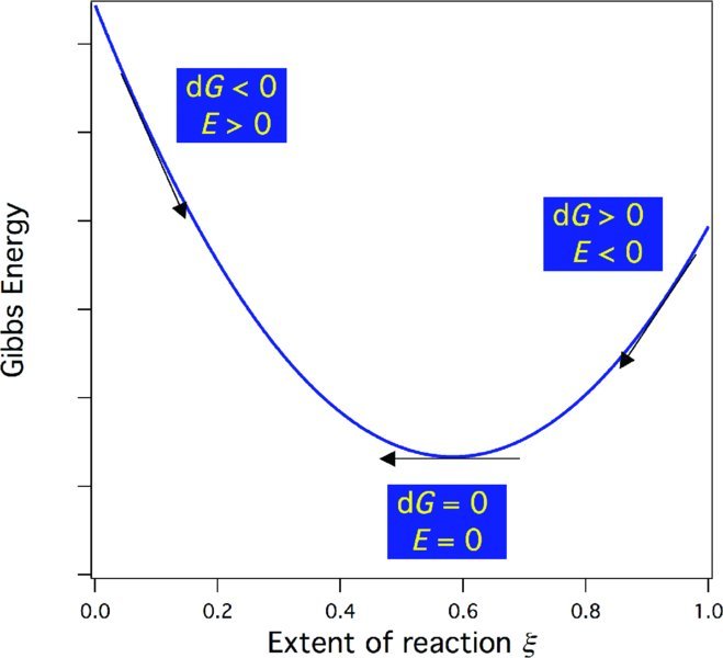
Figure 15.8 The Gibbs energy, its relationship to E, and the direction of spontaneous change. Here, the extent of reaction ξ is normalized to the initial amount of the limiting reagent in moles n0 so that ξ/n0 varies from 0 (no reaction) to 1 (reaction to completion).
15.4.1 The Nernst equation
We now relate the emf to composition. For the Daniell cell above, the cell reaction is

Stay updated, free articles. Join our Telegram channel

Full access? Get Clinical Tree


