Phase stability and phase transitions
12.1 Phase diagrams and the relative stability of solids, liquids, and gases
Did you ever ask yourself why icebergs created from the saltwater of oceans are composed of pure water? What happened to the salt in the saltwater? The process of crystallization, the freezing of water ice from aqueous solutions, naturally expels impurities. We shall see that this occurs because the chemical potentials of solvents and the solutes act differently at the temperature of the phase transition. Once a species is more stable in another phase – that is, once its chemical potential is lower in the other phase – the species makes a transition and passes from one phase to the other. This is the basis of a whole raft of purification techniques: crystallization brought about by lowering temperature; distillation by raising temperature and/or decreasing pressure; and condensation caused by pressure swings.
In the absence of intermolecular forces there would only be ideal gases. The very existence of liquids and solids requires molecules and atoms of finite extent that interact through attractive and repulsive forces. That these forces are not isotropic lends directionality to intermolecular interactions as well as to definite structures in solvation and crystals. Now we look more deeply into the implications of intermolecular interactions with regard to the stability of phases.
A phase is a macroscopically homogeneous region of a system, within which all of the intensive variables vary continuously. If the system is composed of two or more phases, the phases are separated by the formation of interfaces between the different phases. At least some of the intensive variables that describe the system vary discontinuously across these interfaces. A phase transition (also called phase change) is the process of transferring matter across the interface between phases. A congruent transition – including phase transitions between the two-phase equilibria of melting, vaporization, or allotropism of a compound – involves phases of the same composition. Conjugate phases are two phases of variable composition in mutual thermodynamic equilibrium.
The most familiar phase transitions are melting and vaporization. The change in volume upon heating is described by the volume expansion coefficient, αV. For cubic materials the volume expansion coefficient is three times the linear expansion coefficient, αl. Most materials expand upon melting. For a number of metals shown in Table 12.1, we see that expansion upon melting ranges from about 3% to 8%, but this is not universally so and five such examples are also given in Table 12.1. This, of course, means that the density of the solid is less than the density of the liquid at the melting point. Therefore, silicon ‘ice cubes’ float in molten silicon just as do water ice cubes in a glass of sparkling water; while solid gold sinks to the bottom of a container filled with molten gold. This is important for fish in lakes because water ice floats to the top of lakes (and rivers) forming an insulating barrier that slows further freezing, rather than dropping to the bottom of the lake where they would promote faster freezing in the winter and increase the probability of never melting in the summer.
Table 12.1 Melting point Tf, density of solid ρs at 25 °C and Tf, density of the liquid at Tf ρl, coefficient of linear expansion αl for various materials. %Δ = (ρs(Tf) − ρl)/ρs(Tf). Values taken from the 96th edition of CRC Handbook of Chemistry and Physics, except for ρs(Tf), which is calculated assuming αl is constant up to Tf.
| Symbol | Tf / K | ρs(25 °C)/kg m–3 | ρs(Tf)/kg m–3 | ρl/kg m–3 | αl × 106/K–1 | %Δ |
|---|---|---|---|---|---|---|
| H2O | 273.15 | 916.7 | 999.85 | –9.1 | ||
| Bi | 544.56 | 979 | 969.4 | 1050 | 13.4 | –8.3 |
| Ga | 302.92 | 591 | 590.8 | 608 | 18 | –2.9 |
| Ge | 1211.40 | 532.3 | 524 | 560 | 5.8 | –6.9 |
| Si | 1687.15 | 232.9 | 230.4 | 257 | 2.6 | –11.5 |
| Ag | 1234.93 | 1050 | 997 | 932 | 18.9 | 6.5 |
| Al | 933.47 | 270 | 2586 | 2377 | 23.1 | 8.1 |
| Au | 1337.33 | 1930 | 1848 | 1731 | 14.2 | 6.3 |
| Fe | 1811.05 | 787 | 747 | 703.5 | 11.8 | 5.8 |
| Pb | 600.61 | 1130 | 1101 | 1066 | 28.9 | 3.2 |
| Pt | 2041.35 | 2150 | 2055 | 1977 | 8.8 | 3.8 |
| V | 2183.15 | 600 | 572.8 | 550 | 8.4 | 4.0 |
The enthalpy of a phase transition is sometimes also called the latent heat, though this is not the preferred term any longer. The entropy of a phase transition is the enthalpy divided by the temperature, which in this case is
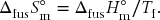
While the enthalpy change upon fusion varies by almost a factor of 1000 for the materials listed in Table 12.1, the entropy change varies by only about a factor of 5. Nonetheless, there is considerable variation in ΔfusS°m that is related to the structure of the material and the nature of the solid-to-liquid transition. The entropy change upon fusion is of the order R (≈ 10 J K–1 mol–1) for simple substances, such as metals and solid covalent diatomics, but increases with increasing molecular complexity, for example ionic compounds and polyatomics.
Note that for all of the substances listed in Table 12.2, the phase transition is that of a crystalline solid to a liquid. A crystalline (or polycrystalline) solid is distinct from a liquid. The crystal possesses definite order and symmetry. A liquid has no long-range order and is isotropic. The two are separated by a normal first-order phase transition – one in which the enthalpy and density change discontinuously between the two phases. An example of such a discontinuous transition is shown in Fig. 12.1 for the melting of water.
Table 12.2 Characteristics of the melting transition for various substances at standard pressure. Values of Tf and ΔfusH°m taken from the 96th edition of CRC Handbook of Chemistry and Physics. ΔfusS°m calculated according to Eq. (12.1).
| Symbol | Tf / K | ΔfusH°m / kJ mol–1 | ΔfusS°m / J K–1 mol–1 |
|---|---|---|---|
| Ar | 83.81 | 1.18 | 14.08 |
| Xe | 161.40 | 2.27 | 14.06 |
| C(graphite) | 4762.15 | 117.40 | 24.65 |
| Si | 1687.15 | 50.21 | 29.76 |
| Hg | 234.32 | 2.29 | 9.79 |
| H2 | 13.99 | 0.12 | 8.58 |
| O2 | 54.36 | 0.44 | 8.09 |
| NaCl | 1073.85 | 28.16 | 26.22 |
| HgCl2 | 550.15 | 19.41 | 35.28 |
| ZnCl2 | 598.15 | 10.30 | 17.22 |
| H2O | 273.15 | 6.01 | 22.00 |
| CO2 | 216.59 | 9.02 | 41.65 |
| NH3 | 195.42 | 5.66 | 28.96 |
| CH4 | 90.68 | 0.94 | 10.37 |
| C2H6 | 90.36 | 2.72 | 30.10 |
| C3H8 | 85.52 | 3.50 | 40.93 |
| C4H10 | 134.85 | 4.66 | 34.56 |
| C2H5OH | 159.01 | 4.93 | 31.01 |
| C6H6 | 278.64 | 9.87 | 35.42 |

Figure 12.1 The change in molar volume as a function of temperature and phase for water near melting transition. Values taken from the 96th edition of the CRC Handbook of Chemistry and Physics.
A glass and a liquid are not distinct phases. They are separated by a second-order phase transition in which properties change sometimes dramatically within a small temperature range. However, the change is not discontinuous. The difference can be traced back to their structure. Just as a liquid is isotropic with no long-range order, so too is a glass. The glass softens and gradually transitions to the liquid, without discontinuous changes. In particular, there is no sharp change in the entropy or molar volume of a glass and a liquid. In contrast, the change in structural order between a solid and a liquid is distinct and accompanied by a significant change in entropy and molar volume.
The enthalpy change upon vaporization ΔvapH°m varies by about 400 for the materials presented in Table 12.3. This represents somewhat less variation than for melting. However, the ΔvapS°m exhibits much less variation than ΔfusS°m, with a factor of just 1.7 covering the spread in values in Table 12.3 (when one excludes the anomalous case of H2, for which quantum corrections to the rovibrational state distribution must be considered). The entropy change upon vaporization is ∼ 85 J K–1 mol–1, which is a statement known as Trouton’s rule. However, Hildebrand’s rule is more accurate, as it states that all liquids have the same value of ΔvapS°m when vaporization occurs at a temperature for which the vapor density is the same. A value of 93 J K–1 mol–1 for ρg = 0.0202 mol l–1 is a rough approximation. We can understand the greater regularity of the entropy change for vaporization by recognizing that the entropy change is dominated by the character of the (nearly) ideal gas that is formed in each case
Table 12.3 Characteristics of the vaporization transition for various substances at standard pressure. * indicates that neither graphite nor CO2 vaporizes because both sublime, and the transition temperature given for these two is for sublimation. Values of Tb and ΔvapH°m taken from the 96th edition of CRC Handbook of Chemistry and Physics. ΔvapS°m calculated analogously to Eq. (12.1).
| Symbol | Tb / K | ΔvapH°m / kJ mol–1 | ΔvapS°m / J K–1 mol–1 |
|---|---|---|---|
| Ar | 87.3 | 6.43 | 73.65 |
| Xe | 165.1 | 12.57 | 76.15 |
| C (graphite) | 4098.1 | * | * |
| Si | 3538.2 | 359.00 | 101.47 |
| Hg | 629.8 | 59.11 | 93.86 |
| H2 | 20.4 | 0.90 | 44.14 |
| O2 | 90.2 | 6.82 | 75.61 |
| NaCl | 1738.2 | 204.50 | 117.65 |
| HgCl2 | 577.1 | 58.90 | 102.05 |
| ZnCl2 | 1005.1 | 126.00 | 125.35 |
| H2O | 373.1 | 40.65 | 108.95 |
| CO2 | 194.7 | * | * |
| NH3 | 239.8 | 23.33 | 97.28 |
| CH4 | 111.7 | 8.19 | 73.34 |
| C2H6 | 184.5 | 14.69 | 79.60 |
| C3H8 | 231.0 | 19.04 | 82.41 |
| C4H10 | 272.6 | 22.44 | 82.30 |
| C2H5OH | 351.4 | 38.56 | 109.72 |
| C6H6 | 353.2 | 30.72 | 86.97 |
12.2 What determines relative phase stability?
Having defined the chemical potential in Chapter 11, we now know what our control parameter is and how to define equilibrium.
At equilibrium the chemical potential of a substance is the same throughout the sample, regardless of how many phases are present.
In other words, the chemical potentials of all phases that are in contact are equal at equilibrium.
Another way to state this criterion for stability is that the Gibbs energy must be minimized. The molar Gibbs energy Gm and the chemical potential μ are synonymous for a one-component system. We write for a pure substance

We substitute for Gm from the fundamental equation and express this in differential form as

Since these are exact differentials, we can express how the chemical potential changes with temperature at constant pressure (dp = 0) according to the partial differential

and how the chemical potential changes with pressure at constant temperature (dT = 0) according to the partial differential

Since the molar entropy and molar volume of a gas are much greater than for the other two phases, it is clear from Eqs. (12.4) and (12.5) that the chemical potential of a gas responds to changes of temperature and pressure more sensitively than for liquids and gases. The importance of this can be observed directly in a plot of chemical potential versus temperature, as shown in Fig. 12.2. The partial derivative represents the slope of the curve. Each phase has its own characteristic dependence of molar entropy on temperature. Nonetheless, we know that the molar entropy of a gas is greater than that of a liquid at the same temperature. Similarly, the molar entropy of a liquid is always greater than that of a solid of the same material at the same temperature. Stated mathematically, at any given temperature 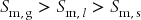 .
.

Figure 12.2 Chemical potential–T phase diagram for a material with properties approximately those of water.
The molar entropy of each phase is a function of temperature. In accord with Eq. (12.4) the chemical potential versus temperature of each phase is represented by a curve, as shown in Fig. 12.2.
A system is at equilibrium when its chemical potential is a minimum.
The lowest chemical potential phase is the most stable at any given temperature and pressure. Figure 12.2 represents the chemical potential versus temperature at the standard pressure of p° = 1 bar. The curve that represents the chemical potential of the solid starts with a slope of zero at absolute zero. This is the behavior of all perfect crystals according to the Third Law of Thermodynamics. The slope becomes increasingly negative. At the standard melting point, Tf, the chemical potentials of the solid and liquid phases are equal, μ(s) = μ(l) at Tf. At this point the curve for the chemical potential of the solid intersects the curve for the chemical potential of the liquid. We do not need to know the absolute value of either slope; however, we do know that the slope of the liquid curve is greater than the slope of the solid curve. Similarly, at the standard boiling point Tb, the chemical potentials of the liquid and gas phases are equal, μ(l) = μ(g) at Tb. At this point the curve for the chemical potential of the liquid intersects the curve for the chemical potential of the gas, and the slope of the gas curve is greater than the slope of the liquid curve.
Figure 12.2 demonstrates behavior that in one sense is universal, and in another sense is normal but not always observed. The universal behavior is this:
When the chemical potential of one phase drops below the chemical potential of another, the lower chemical potential phase is more stable.
Figure 12.2 represents a chemical potential–T or μ–T phase diagram. The point at which their chemical potentials are the same is the point at which the phase transition occurs at equilibrium. However, we should not conclude that melting always precedes vaporization. Indeed, a direct consequence of Eq. (12.5) is that sublimation can occur rather than the ‘normal’ ordering of melting followed by vaporization.
According to Eq. (12.5) the chemical potential of a gas is quite sensitive to changes in pressure. Integration of Eq. (12.5) with dT = 0 shows us that the chemical potential of an ideal gas increase with increasing pressure according to

where μ°g is the chemical potential of an ideal gas at the standard state pressure of p° = 1 bar.
Because the molar volumes of the liquid and solid are roughly 1000-fold smaller than the molar volume of the gas, the chemical potentials of liquids and solids are almost independent of pressure when compared on the same scale as the gas. Assuming that the liquid is incompressible – that is, that molar volume is independent of pressure – integration of Eq. (12.5) yields

A similar equation holds for the solid phase in which the molar volume of the solid Vm,s replaces the molar volume of the liquid Vm,l, and similarly for the standard potential of the solid μ°s and that of the liquid μ°l.
Now look back at Fig. 12.2. When the pressure is increased, the solid and liquid curves shift only slightly, but the gas curve shifts significantly lower as the pressure is increased. At sufficiently high pressure, the gas curve will shift so far that it intersects the solid curve before the liquid curve. In such a case, the material sublimes (transitions from solid to gas) rather than melts. At atmospheric pressure, this is true of carbon dioxide, which sublimes at Tsp = 195 K, some organic compounds, such as caffeine with Tsp = 363 K, and graphite with Tsp = 3825 K.

Figure 12.3 Chemical potential versus pressure. The chemical potential of a gas varies strongly with pressure. While not independent of pressure, the changes for liquids and gases are insignificant when compared to those of gases over the same range.
There is another consequence of Fig. 12.3. The chemical potential of a gas can be reduced without limit by reducing its pressure. But this is not the case for solids and liquids, and therefore a means of stabilizing a component in the gas phase exists that does not exist for the other two phases. At any given temperature a gas is able to coexist with either of the condensed phases. It achieves this by adjusting its pressure to the equilibrium vapor pressure of the material. In all cases, the vapor is in equilibrium with the liquid or the solid; however, as the temperature is reduced the equilibrium vapor pressure of the gas must decrease to maintain the equality of chemical potential with the condensed phase.
This is a very important result. How do we measure the chemical potential? In the abstract this is a difficult question to answer. However, Eq. (12.6) shows us that it is very simple for an ideal gas: We simply measure the equilibrium partial pressure of the gas. Furthermore, since the chemical potential of all phases must be equal at equilibrium, then an equilibrium measurement of vapor pressure also allows us to quantify the chemical potential of any other phase (e.g., pure liquid, solution or solid) that is in contact with this vapor phase.
12.2.1 Directed practice
Derive Eqs. (12.6) and (12.7) by substituting for Vm and using a standard state pressure of p° = 1 bar.
12.3 The p–T phase diagram
If one plots the equilibrium vapor pressure of a liquid as a function of temperature, a curve such as that displayed in Fig. 12.4 is obtained. We see that the curve is continuous throughout the temperature range, extending from the melting point to the critical point.
The standard boiling point is defined as the temperature at which the vapor pressure is equal to the standard pressure of 100 kPa.

Figure 12.4 The curve that describes the equilibrium vapor pressure of water vapor above liquid water represents the coexistence boundary between these two phases. Data taken from 96th edition of the CRC Handbook of Chemistry and Physics.
As far as the relationship of vapor pressure to temperature, the boiling point is not a special point.
One, two, or threes phase of a pure substance of fixed composition can coexist. A pressure–temperature phase diagram shows us graphically what phases are stable for any combination of p and T. By inspection of such a curve, you are able to identify a coexistence curve, standard boiling point, standard melting point, the triple point, and critical point.
The boundary lines in the p–T phase diagram define the coexistence curves. These are the combinations of pressure and temperature at which two phases can be in equilibrium with one another. The standard transition temperature corresponds to the temperature at which a particular phase transition occurs when the pressure is equal to the standard pressure of 1 bar. The triple point is a unique point in a p–T phase diagram. It is the only combination of pressure and temperature at which the solid, liquid, and gas phases can coexist at equilibrium. Note one other thing about the triple point. If the triple point corresponds to a pressure below standard pressure, then the material exhibits a ‘normal’ μ versus T phase diagram such as that shown in Fig. 12.2. The solid melts to a liquid and the liquid vaporizes into the gas as T is increased. If, on the other hand, the substance has a triple point that occurs above p = 1 bar, then the solid sublimes before it melts.
The water phase diagram also exhibits the presence of different crystal modifications or polymorphs – different crystalline forms of the same composition. There are several solid forms of water ice. The presence of two is shown in Fig. 12.6. Only one crystal modification of water is known at atmospheric pressure; all of the others form at higher pressure. The presence of multiple crystal modification means that the phase diagram also exhibits points where two solid phases and the liquid phase intersect. This is a type of triple, however ‘the triple point’ is the point at which solid, liquid, and gas intersect. If the point in question refers to a different triple intersection of a different set of phases, those phases should be specified. Many other materials exhibit multiple crystal modifications, such as carbon (diamond and graphite), tin (α-Sn and β-Sn, also called ‘gray’ tin and ‘white’ tin), phosphorus (red and white phosphorus among others), SiO2 (quartz, cristobalite, tridymite and stishovite to name a few) and Al2O3 (corundum and γ-Al2O3).

Figure 12.5 The curve that describes the equilibrium vapor pressure of water vapor above solid water represents the coexistence curve for sublimation. Data taken from 96th edition of the CRC Handbook of Chemistry and Physics.

Figure 12.6 p–T phase diagram of water.
The critical point is another special point in the p–T phase diagram. It occurs at the combination of temperature and pressure when the density of the gas phase is the same as the density of the liquid phase. At this point, the molecules in the two phases are on average the same distance apart and experience the same intermolecular forces; in other words, the two phases are indistinguishable. Thus, other properties such as the heat capacity and molar entropy of the liquid and gas also converge on each other and become indistinguishable. This can be seen in Fig. 12.5 using data for H2O. Both, the entropy and enthalpy changes go to zero for the transition liquid  gas at the critical point, which means that there is no longer a phase transition at and after the critical point. At the critical point and beyond the fluid is called a supercritical fluid. It is a fluid that exists beyond the critical point.
Look at the temperature dependence of ΔvapH°m. As expected, the enthalpy change depends on temperature, and this dependence is at first linear in T. This is the range for which the correction factor is ΔrCp,m ΔT. As the temperature approaches the critical temperature, the difference in heat capacities drops to zero. The change in ΔrCp,m from some finite value to zero is a general phenomenon; thus, we expect curvature of the type observed in Fig. 12.7 to develop for all gases as they approach Tc.

Figure 12.7 Enthalpy and entropy of vaporization of water from 273.16 K (standard melting point) to 647.10 K (critical temperature) at standard pressure.
A supercritical fluid has a number of remarkable properties. One property is that its existence allows a system to pass from the liquid phase to gas phase along a path that does not include a phase transition. This is extremely important for the field of nanoscience. A technique called critical point drying depends on this phenomenon. Ethanol and carbon dioxide are miscible and form a supercritical fluid. Imagine we have a sample – it could be an insect or cell or a nanomaterial – that we want to image to observe its nanoscale details. If the sample is wet because it was made in an aqueous solution, or has fluid inside of it as for the insect or cell, then the small features are subjected to capillary forces that occur when fluids evaporate. The magnitude of these forces increases rapidly as the curvature increases. The equivalent of hundreds or even thousands of atmospheres of pressure can act on the nanoscale features as a result, and this will distort or even destroy the sample.
Instead of allowing the sample to dry in air, we replace the water with ethanol. Then, the sample in ethanol is placed within a stainless steel vessel that can be heated and pressurized with CO2. The pressure is raised to at least 83 bar at room temperature, after which the temperature is raised to approximately 35 °C. The fluid becomes supercritical. At the elevated temperature, the pressure is reduced such that the gas phase is established, and the temperature is then reduced. Using this procedure, the solution has been removed from the sample without the sample ever experiencing capillary forces. The results of not using such a drying procedure are shown in Fig. 12.8, in which a porous silicon thin film has cracked and exfoliated under the influence of destructive capillary forces.

Figure 12.8 Critical point drying is essential for avoiding the deleterious effects of capillary forces on nanomaterials. In this example, exfoliation has occurred, ripping the top of a highly porous nanocrystalline silicon film from a region of the film with lower porosity. The lower portion remains attached to the crystalline Si substrate. For details. see Dudley, M.E. and Kolasinski, K.W. (2009) Electrochem. Solid State Lett., 12, D22. Reproduced with permission from The Electrochemical Society.
12.4 The Gibbs phase rule
At equilibrium, all phases that exist must have the same chemical potential. In a single-phase region, T and p can be varied independently, but when two phases α and β coexist the constraint on the chemical potential,

Stay updated, free articles. Join our Telegram channel

Full access? Get Clinical Tree


