Automation in the Clinical Laboratory

Chapter 19


Automation in the Clinical Laboratory


The term automation has been applied in clinical chemistry to describe the process whereby an analytical instrument performs many tests with only minimal involvement of an analyst. The availability of automated instruments enables laboratories to process much larger workloads without comparable increases in staff. The evolution of automation in the clinical laboratory has paralleled that in the manufacturing industry, progressing from fixed automation, whereby an instrument performs a repetitive task by itself, to programmable automation, which allows the instrument to perform a variety of different tasks. Intelligent automation also has been introduced into some individual instruments or systems to allow them to self-monitor and respond appropriately to changing conditions.


One benefit of automation is a reduction in the variability of results and errors of analysis through the elimination of tasks that are repetitive and monotonous for most individuals. The improved reproducibility gained by automation has led to a significant improvement in the quality of laboratory tests.


Many small laboratories now have consolidated into larger, more efficient entities in response to market trends involving cost reduction. The drive to automate these mega-laboratories has led to new avenues in laboratory automation. No longer is automation simply being used to assist the laboratory technologist in test performance; it now includes (1) processing and transport of specimens, (2) loading of specimens into automated analyzers, (3) assessment of the results of the tests performed, and (4) storage of specimens. We believe that automating these additional functions is crucial to the future prosperity of the clinical laboratory.1,2


This chapter discusses the principles that apply to automation of the individual steps of the analytical process—both in individual analyzers and in the integration of automation throughout the clinical laboratory.


Basic Concepts


Automated analyzers generally incorporate mechanized versions of basic manual laboratory techniques and procedures. However, modern instrumentation is packaged in a wide variety of configurations. The most common configuration is the random-access analyzer. In random-access analysis, analyses are performed sequentially on a collection of specimens, with each specimen analyzed for a different selection of tests. Tests performed in random-access analysis are selected through the use of different vials of reagents stored on board the analyzer. This approach permits measurement of a variable number and variety of analytes in each specimen. Profiles or groups of tests are defined for a specimen at the time the tests to be performed are entered into the analyzer (1) via a keyboard, (2) by instruction from a laboratory information system in conjunction with bar coding on the specimen tube, or (3) by operator selection of appropriate reagent packs.


Historically, other analyzer configurations used include continuous-flow and centrifugal analyzers. Continuous-flow analyzers were the first automated analyzers used in clinical laboratories. Initially, these analyzers were used in a single-channel analysis configuration and carried out a sequential analysis of each specimen. Subsequently, multiple-channel analysis versions were developed, in which analysis of each specimen was performed on every channel in parallel. Results from nonrequested tests in the test profile were discarded as necessary after the analysis was complete. Inflexibility in the menu of tests that could be performed on these analyzers eventually led to their replacement in the marketplace by more versatile configurations.


Centrifugal analyzers used discrete pipetting to load aliquots of specimens and reagents sequentially into the discrete chambers in a rotor, and the specimens subsequently were analyzed in parallel (parallel analysis) by spinning the rotor to exert centrifugal force to mix the specimens and reagent and to drive the mixtures into cuvettes located on the periphery of the rotor. Such analyzers could be operated in a multiple-specimen/single-chemistry or a single-specimen/multiple-chemistry mode. Although such technology was developed as part of the space program and is suitable for application in a zero gravity environment, it was not sufficiently versatile to compete with other random-access analyzers and has largely been abandoned for use in the routine laboratory.


Automation of the Analytical Processes


The following individual steps required to complete an analysis often are referred to collectively as unit operations (Box 19-1). These operations are described individually in this section, and examples demonstrate how they have been automated in terms of operational and analytical performance. In most automated systems, these steps usually are performed sequentially, but with some instruments, they may occur in parallel.


Specimen Identification


Typically, the identifying link (identifier) between patient and specimen is noted at the patient’s bedside, and maintenance of this connection throughout (1) transport of the specimen to the laboratory, (2) subsequent specimen analysis, and (3) preparation of a report is essential. Several technologies are available for automatic identification and data collection purposes (Box 19-2). In practice, automatic identification includes only those technologies that electronically detect a unique characteristic or unique data string associated with a physical object. For example, identifiers such as (1) serial number, (2) part number, (3) color, (4) manufacturer, (5) patient name, and (6) medical record number have been used to identify an object or patient through the use of electronic data processing. In the clinical laboratory, labeling with a bar code has become the technology of choice for purposes of automatic identification.


Labeling


In many laboratory information systems, electronic entry of a test order in the laboratory or at a nursing station for a uniquely identified patient generates a specimen label bearing a unique laboratory accession number. A record is established that remains incomplete until a result (or a set of results) is entered into the computer against the accession number. The unique label is affixed to the specimen collection container when the specimen is obtained. Proper alignment of the label on a specimen tube is critical for subsequent specimen processing when bar-coded labels are used. Arrival of the specimen in the laboratory is recorded by a manual or computerized log-in procedure. In other systems, the specimen is labeled at the patient’s bedside, and patient identification and collection information is provided; then the labeled specimen is submitted to the laboratory with a requisition form. There it is assigned an accession number as part of the log-in procedure, which is usually a computerized process.


After accessioning, specimens undergo the technical handling processes. For those processes requiring physical removal of serum or plasma from the original tube, secondary labels bearing essential information from the original label must be affixed to any secondary tubes created. Some automated analyzers sample directly from the original collection tube while simultaneously reading the accession number from the bar code label on the tube. Secondary bar code labels, if necessary, may be generated at the time of accessioning, or in some analyzers by a built-in printer that is activated when the analyzer is programmed.


Many methods are used to achieve secondary labeling when bar code labels are not available. A number may be handwritten on the specimen cup, or a coded label may be affixed to the original tube or to a specimen cup. The label numbers require correlation with a manual or computer-generated work or load list. The load list usually records accession numbers in sequence with the physical positions of cups or tubes in the loading zone of the analyzer. This loading zone may be (1) a revolving tray or turntable, (2) a mechanical belt, or (3) a rack or set of racks by which specimens are delivered in a predetermined order to the sample aspiration station of the analyzer.


In those analyzers that do not automatically link specimen identity and sample aspiration, the sequence of results produced must be linked manually with the sequence of entry of specimens. Some analyzers print out or transmit to a host computer each result or set of results from a specimen through the position of the specimen in the loading zone or the accession number programmed to that position.


Bar Coding


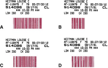
A major advance in the automation of specimen identification in the clinical laboratory is the incorporation of bar coding technology into analytical systems. A bar coding system consists of a bar code printer and a bar code reader, or scanner. One- and two-dimensional bar coding systems are available. A one-dimensional bar code is an array of rectangular bars and spaces arranged in a predetermined pattern according to unambiguous rules to represent elements of data referred to as characters. A bar code is transferred and affixed to an object by a bar code label that carries the bar code and, optionally, other noncoded readable information. Symbology is the term used to describe the rules specifying the way data are encoded into the bars and spaces. The width of the bars and spaces, as well as the number of each, is determined by a specification for that symbology. Different combinations of bars and spaces represent different characters. When a bar code scanner is passed over the bar code, the light beam from the scanner is absorbed by the dark bars and is not reflected; the beam is reflected by the light spaces. A photocell detector in the scanner receives the reflected light and converts that light into an electrical signal that then is digitized. A one-dimensional bar code is “vertically redundant” in that the same information is repeated vertically—the heights of the bars can be truncated without any loss of information. In practice, vertical redundancy allows a symbol with printing defects, such as spots or voids, to be read.


In practice, a bar code label (often generated by the laboratory information system and bearing the sample accession number) is placed onto the specimen container and is subsequently “read” by one or more bar code readers placed at key positions in the analytical sequence. The resultant identifying and ancillary information then is transferred to and processed by the system software. Initiating bar code identification at a patient’s bedside ensures greater integrity of the specimen’s identity in an analyzer. Systems to transfer information concerning a patient’s identity to blood tubes at the patient’s bedside have been introduced in many hospitals, and several companies are now offering these systems.


Unequivocal positive identification of each specimen is achieved in analyzers with bar code readers. Advantages of the use of bar code labels include the following:


Examples of types of bar codes that are used in chemistry analyzers are illustrated in Figure 19-1.


Identification Errors


Many opportunities arise for the mismatch of specimens and results. The risks begin at the bedside and are compounded with each processing step a specimen undergoes between collection from the patient and analysis by the instrument. The risks are particularly great when hand transcription is invoked for accessioning, labeling and relabeling, and creation of load lists. An incorrect accession number, one in which the digits are transposed, or a load list with transposed accession numbers may cause test results to be attributed to the wrong patient. An additional hazard exists when specimens must be inserted into certain positions in the loading zone defined by a load list. Human misreading of the specimen label or the loading list may cause misplacement of specimens, calibrators, or controls. Automatic reading of bar code labels reduces the error rate from 1 in 300 characters (for human entry) to about 1 in 1 million characters barring (1) minor imperfections in printed bar codes, (2) improper bar code scanner resolution, or (3) skewed orientation of bar code labels on containers, all of which can result in read errors.


Specimen Preparation


The clotting of blood in specimen collection tubes, their subsequent centrifugation, and the transfer of serum to secondary tubes require a finite time to complete. If performed manually, the process results in a delay in the preparation of a specimen for analysis. To eliminate the problems associated with specimen preparation, systems are being developed to automate this process.


Specimen Delivery


Automated methods are often used to deliver specimens to the laboratory instead of the historic method (courier service). These include (1) pneumatic tube systems, (2) electric track vehicles, and (3) mobile robots.


Electric Track Vehicles


Electric track vehicles have a larger carrying capacity than pneumatic tube systems and do not have problems with damaging specimens by acceleration and/or deceleration forces. Some systems maintain the carrier in an upright position with the use of a gimbal (a device that permits a body to incline freely in any direction or suspends it so it will remain level when its support is tipped), enabling the carrier to move both vertically and horizontally on an installed electric track. The containers can hold dry ice or refrigerated gel packs with specimens if desired. They are especially useful in quickly transporting specimens between floors or between laboratory locations that are some distance from each other, by making use of the space in the ceiling plenum above the laboratory. A primary disadvantage is the cost of moving the track and loading/unloading stations if the laboratory is expanding or moving; in addition, the stations may be larger than the pneumatic tube stations. If the station is not located directly in the central laboratory (centralized testing; core laboratory), additional staff may be necessary to unload the carts and transport the specimens to their final destination, and the electric track system may not achieve its desired goal of rapid specimen transport.


Mobile Robots


Automated guided vehicles (AGVs), also called mobile robots, have been used successfully to transport laboratory specimens both within the laboratory and outside the central laboratory.13 They are easily adapted to carry various sizes and shapes of specimen containers and are reprogrammable with changes in laboratory geometry. In addition, in a busy laboratory setting, delivery of specimens to laboratory benches by a mobile robot can be more frequent than human pickup and has been shown to be cost-effective. Inexpensive models follow a line on the floor, whereas others have more sophisticated guidance systems. Their limitations include the need to batch specimens for greater efficiency and, in most cases, the requirement for laboratory personnel to place specimens onto or remove specimens from the mobile robot at each stopping place. Some mobile robots have been integrated with robotic systems that automate loading and unloading of specimens; others initiate an audible or visual signal of their arrival at a specified station so that employees are able to load or unload the specimens being transported. Box 19-3 lists several vendors that provide mobile robot systems for clinical laboratories.


Specimen Loading and Aspiration


In most situations, the specimen for automatic analysis is serum or plasma. Many analyzers directly sample serum from primary collection tubes of various sizes. With such analyzers, the collection tubes most frequently used contain separator material that forms a barrier between serum or plasma and cells (see Chapter 7).


Many analyzers also sample from cups or tubes filled with serum transferred from the original specimen tubes. Often the design of the sampling cup is unique for a particular analyzer. Each cup should be designed to minimize dead volume, that is, the excess serum that must be present in a cup to permit aspiration of the full volume required for testing. Cups must be made of inert material so they do not interact with the analytes being measured. Specimen cups also should be disposable to minimize cost and contamination, and their shape should, even without a cap, minimize evaporation by minimizing the surface area of sample exposed to the air.


Specimens may undergo other forms of degradation in addition to evaporation. For example, specimens that contain thermolabile constituents may undergo degradation of such analytes if held at ambient temperatures. Other constituents, such as bilirubin, are photolabile. Thermolability is minimized when both specimens and calibrators are held in a refrigerated loading zone. Photodegradation is reduced by the use of semiopaque cups and placement of smoke- or orange-colored plastic covers over the specimen cups.


The loading zone of an analyzer is the area in which specimens are held in the instrument before they are analyzed. The holding area may be a circular tray, a rack or series of racks built into a cassette, or a serpentine chain of containers into which individual tubes are inserted. When specimens are not identified automatically, they must be presented to the sampling device in the correct sequence, as specified by a loading list. The sampling mechanism determines the exact volume of sample removed from the specimen.


For most analyzers, specimens for a subsequent run may be prepared on a separate tray while one run is already in progress. This process permits machine operation and human actions to proceed in parallel for optimal efficiency. In some analyzers, specimens may be added continuously by the operator as they become available. A desirable feature of any automated analyzer is the ability to insert new specimens ahead of specimens already in place in the loading zone. This feature allows the timely analysis of a specimen with a high medical priority. When specimen identification is machine-read, it is possible for the operator to easily reposition specimens in the loading zone. When specimen identification is tied to a loading list, however, insertion or repositioning of specimens must be accompanied by revision of the loading list.


Transmission of infectious diseases by automated equipment is a concern in clinical laboratories. The method of transmission by equipment is primarily through splatter of serum or blood during the acquisition of samples from rapidly moving specimen probes. The use of level sensors, which restrict the penetration of sample probes into specimens, and provision of software for smoother motion control greatly reduce splatter.


Because the potential for contamination exists when the stoppers of primary containers are opened or “popped” to decant serum into specimen cups, several firms have developed closed-container sampling systems for use in their automated hematology and chemistry analyzers. In these systems, the specimen probe passes through a hollow needle that initially penetrates the primary container’s rubber stopper. This configuration prevents damage or plugging of the specimen probe while allowing the level sensor (used to reduce carryover and to detect short samples) to remain active. After the specimen probe is withdrawn, the outer hollow needle also is withdrawn, so the stopper reseals and no specimen escapes. Closed-container sampling is used widely in hematology analyzers.


Sample Introduction and Internal Transport


The method used to introduce the sample into the analyzer and its subsequent transport within the analyzer is the major difference between continuous-flow and discrete systems. In continuous-flow systems, the sample is aspirated through the sample probe into a stream of flowing liquid, whereby it is transported to analytical stations in the instrument. In discrete analysis, the sample is aspirated into the sample probe and then is delivered, often with reagent, through the same orifice into a reaction cup or other container. Carryover is a potential problem with both types of systems.


Technicon Instruments Corporation pioneered the use of peristaltic pumps and plastic tubing to advance the sample and reagents in continuous-flow analysis. Peristaltic pumps trap a “slug” of fluid between two rollers that occlude the tubing. As the rollers travel over the tubing, the trapped fluid is pushed forward and, as the leading roller lifts from the tubing, is added to the fluid beyond it. The peristaltic pump still is used in some hematology analyzers and analyzers with ion-selective electrodes, as well as for wash systems.


Discrete Processing Systems


Positive–liquid displacement pipettes are used for sampling in most discrete automated systems in which specimens, calibrators, and controls are delivered by a single pipette to the next stage in the analytical process.


A positive-displacement pipette may be designed for one of two operational modes: (1) to dispense only aspirated sample into the reaction receptacle, or (2) to flush out sample together with diluent. Both systems use a plastic or glass syringe with a plunger, the tip of which usually is made of Teflon.


Pipettes may be categorized as (1) fixed-, (2) variable-, or (3) selectable-volume (see Chapter 9). Selectable-volume pipettes allow the selection of a limited number of predetermined volumes. Pipettes with unlimited or selectable volumes are used in systems that allow many different applications, whereas fixed-volume pipettes usually are used for samples and reagents in instruments dedicated to the performance of only a small variety of tests.


Carryover


Carryover is defined as the transfer of a quantity of analyte or reagent from one specimen reaction into a subsequent one. Because it erroneously affects analytical results from the subsequent reaction, carryover should be minimized or eliminated. In discrete systems with disposable reaction vessels and measuring cuvets, carryover is caused by the pipetting system. In instruments with reusable cuvets or flowcells, carryover may also arise from incomplete cleaning of the cuvettes or flowcells between assays.


Most manufacturers of discrete systems reduce sample-to-sample carryover by using disposable pipette tips or by incorporating wash stations for the sample probe that flush the internal and external surfaces of the probe with copious amounts of diluent. An adequate ratio of flush and rinse to specimen volume controls carryover in many cases to acceptable values. Appropriate choice of sample probe material, geometry, and surface conditions also influences carryover. Some systems wipe the outside of the sample probe to prevent transfer of a portion of the previous specimen into the next specimen cup. Use of disposable sample probe tips allows complete elimination of contamination of one sample by another inside the probe, as well as the carryover of one specimen into the specimen in the next cup, because a new pipette tip is used for each pipetting.


In practice, the reduction of sample-to-sample carryover is a more stringent requirement for automated analyzers that perform immunoassays in which some analytes (e.g., human chorionic gonadotropin) have a wide range of concentrations. Some systems use extra steps, such as additional washes, or an additional washing device to reduce carryover for selected tests to acceptable limits. Because extra steps reduce overall throughput, additional rinsing functions are initiated (by computer operator selection) only for assays with a large analytical measurement range.


Sample-to-sample carryover can be detected by the preparation of two sample pools—one having a very high analyte concentration (H), the other having a low concentration (L). By running sequences of tests such as HHHLLLHHLLHHLL, if sample-to-sample carryover is present, higher results will be noted in the low-concentration sample analyses that immediately follow a high-concentration sample analysis.


Reagent-to-reagent carryover also can occur on discrete systems that use a common reagent probe for pipetting all reagents; its minimization or elimination requires use of the same approaches just described for sample-to-sample carryover. Detection of reagent-to-reagent carryover can be difficult for end-users and usually requires the involvement of the instrument vendor. Users should be aware that the introduction of third party reagents in “open” channels on otherwise closed systems may introduce problems with reagent-to-reagent carryover. Consultation with the system manufacturer is advised to determine how to test for and minimize such carryover.


Reagent Handling and Storage


Many automated systems use liquid reagents stored in plastic or glass containers. For those analyzers in which a working inventory is maintained in the system, the volumes of reagents stored depend on the number of tests to be performed without operator intervention.


For many analyzers in which specimens are not processed continuously, reagents are stored in laboratory refrigerators and are introduced into the instruments as required. In larger systems, sections of the reagent storage compartments are maintained at 4 to 10 °C.


Some systems use reagents or antibodies that have been immobilized in a reaction coil or chamber to allow their repetitive use in a chemical reaction. Other systems use enzymes immobilized on membranes coupled to sensing electrodes. The reaction products then are measured by the sensing device. Only a buffer is required as a diluent and a wash solution; thus the membrane has an extended life, which lowers the cost of each test.


Reagent Identification


Labels on reagent containers include information such as (1) reagent identification, (2) volume of the contents or the number of tests for which the contents of the containers are to be used, (3) expiration date, and (4) lot number. Many reagent containers now carry bar codes that contain some or all of this information, and the manufacturer is able to retrieve any pertinent information when necessary.


Other advantages of using reagent bar codes include (1) facilitation of inventory management, (2) ability to insert reagent containers in random sequence, and (3) ability to automatically dispense a particular volume of liquid reagent. Furthermore, when a bar code reader is coupled with a level-sensing system on the reagent probe, it alerts the operator as to whether a sufficient quantity of reagent exists to complete a workload.


A bar code on a reagent container may also contain information about (multiple) calibrators, such as the definition of a calibration curve algorithm and values of curve constants defined at the time of reagent manufacture. Accompanying calibrator materials provided in their own bar code tubes at the time of manufacture ensure that calibration functions are integrated properly into the analysis.

Stay updated, free articles. Join our Telegram channel

Nov 27, 2016 | Posted by in GENERAL & FAMILY MEDICINE | Comments Off on Automation in the Clinical Laboratory

Full access? Get Clinical Tree

Get Clinical Tree app for offline access