Materials
Standard
Stainless steel
ISO 5832–1, Implants for surgery – Metallic materials – Part 1: Wrought stainless steel
ISO 5832–9, Implants for surgery – Metallic materials – Part 9: Wrought high nitrogen stainless steel
ASTM F138, Standard Specification for Wrought 18Chromium–14Nickel–2.5Molybdenum Stainless Steel Bar and Wire for Surgical Implants
Co–Cr alloy
ISO 5832–4, Implants for surgery – Metallic materials – Part 4: Cobalt–chromium–molybdenum casting alloy
ISO 5832–5, Implants for surgery – Metallic materials – Part 5: Wrought cobalt–chromium–tungsten–nickel alloy
ISO 5832–6, Implants for surgery – Metallic materials – Part 6: Wrought cobalt–nickel–chromium–molybdenum alloy
ISO 5832–7, Implants for surgery – Metallic materials – Part 7: Forgeable and cold-formed cobalt–chromium–nickel–molybdenum–iron alloy
ISO 5832–12, Implants for surgery – Metallic materials – Part 12: Wrought cobalt–chromium–molybdenum alloy
ASTM F75, Standard Specification for Cobalt–28Chromium–6Molybdenum Alloy Castings and Casting Alloy for Surgical Implants
ASTM F90, Standard Specification for Wrought Cobalt–20Chromium–15Tungsten–10Nickel Alloy for Surgical Implant Applications
ASTM F799, Standard Specification for Cobalt–28Chromium–6Molybdenum Alloy Forgings for Surgical Implants
ASTM F1537, Standard Specification for Wrought Cobalt–28Chromium–6Molybdenum Alloys for Surgical Implants
Titanium and titanium alloy
ISO 5832–2, Implants for surgery – Metallic materials – Part 2: Unalloyed titanium
ISO 5832–3, Implants for surgery – Metallic materials – Part 3: Wrought titanium 6–aluminum 4–vanadium alloy
ASTM F67, Standard Specification for Unalloyed Titanium, for Surgical Implant Applications
ASTM F136, Standard Specification for Wrought Titanium–6Aluminum–4Vanadium ELI (Extra Low Interstitial) Alloy for Surgical Implant Applications
ASTM F1108, Standard Specification for Titanium–6Aluminum–4Vanadium Alloy Castings for Surgical Implants
ASTM F1813, Standard Specification for Wrought Titanium–12Molybdenum–6Zirconium–2Iron Alloy for Surgical Implant
Fig. 1.1
Typical products used in artificial hip joint and knee joint. (a) Artificial hip joint. (b) Artificial knee joint
The materials and manufacturing methods used are of critical importance for orthopedic implants, and they need to be selected appropriately depending on the shape, cost, and performance required of the orthopedic implants in actual use.
For example, the stem of a hip joint prosthesis with no bone cement is supposed to adhere to living bone tissue for a long period of time, and therefore, highly biocompatible titanium alloys are selected; because mechanical strength and ductility are required, the forging method is selected as the manufacturing method. On the other hand, the femoral component of artificial knee joint is used on a sliding portion, and therefore, highly abrasion-resistant Co–Cr alloys are selected; because of the complex shape of the prosthesis, the casting process is selected as the manufacturing method. Over the past few decades, Co–Cr and titanium alloys have become the mainstream materials, and the forging procedure and the casting method have become the mainstream manufacturing methods. However, new biomedical metallic materials [19, 20] and novel manufacturing methods [21, 22] are continually being developed. Particularly, the additive manufacturing process has recently attracted attention as a new manufacturing method for orthopedic implants [23]. This chapter describes additive manufacturing technology and the development of orthopedic implants utilizing this technology.
1.2 Additive Manufacturing
Additive manufacturing technology was developed in the early 1980s, and it has been used as a means to accelerate the manufacturing of prototypes and design validation models, mainly in the aircraft and automobile industries, which used three-dimensional (3D) data from early on. Currently, complex shapes can be expressed with dimensional accuracy by using metallic powders and resins as materials. However, initially, thermoplastic resins were melted with heat and laminated, and photo-polymerizing resins were irradiated with ultraviolet light in a hardening-only method; materials were limited and dimensional accuracy was low. Later, with technological advances in additive manufacturing in terms of the diversification of materials and the improvement of dimensional accuracy, the application of additive manufacturing has increased. Research and development of additive manufacturing using metallic powder was popular in the 1990s. In the 2000s, use of the method went beyond creating models for design verification; they were also commonly utilized for the direct creation of prototypes for use in performance tests and assembly, in manufacturing processes, and in small amounts of finished products. Figure 1.2 shows various medical devices made by using the additive manufacturing process.
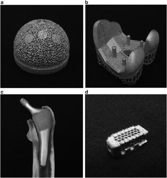
Fig. 1.2
Various medical devices made by using an additive manufacturing process. (a) Acetabular cup. (b) Artificial knee joint. (c) Artificial hip joint. (d) Spine cage
Initially, the process was often called “rapid prototyping” because it allowed for a rapid construction of models; however, as the technology became widespread, it became known under various names, such as additive fabrication (AF), direct digital manufacturing (DDM), free-form fabrication (FFF), and three-dimensional printing (3DP). Therefore, in 2009, ASTM defined it as additive manufacturing (AM), in the sense that it was a manufacturing method consisting of adding materials as opposed to manufacture by removal, such as in cutting [24]. Table 1.2 shows additive manufacturing process categories defined by ASTM F2729-12a. The additive manufacturing processes, which allow for manufacturing metal components, are powder bed fusion and directed energy deposition. Powder bed fusion is a method for constructing three-dimensional structures by using energy sources such as laser beams and electron beams for sintering or melting the starting raw material powder. Depending on the energy source, powder bed fusion is also known as selective laser melting (SLM) or electron beam melting (EBM). Directed energy deposition is a method for manufacturing three-dimensional structures by using a high-power laser to melt the metal powder while stacking it into layers.
Table 1.2
Additive manufacturing process categories
Type | Process |
|---|---|
Binder jetting | An additive manufacturing process in which a liquid bonding agent is selectively deposited to join powder materials |
Directed energy deposition | An additive manufacturing process in which focused thermal energy is used to fuse materials by melting as they are being deposited |
Material extrusion | An additive manufacturing process in which material is selectively dispensed through a nozzle or orifice |
Material jetting | An additive manufacturing process in which droplets of build material are selectively deposited |
Powder bed fusion | An additive manufacturing process in which thermal energy selectively fuses regions of a powder bed |
Sheet lamination | An additive manufacturing process in which sheets of material are bonded to form an object |
Vat photopolymerization | An additive manufacturing process in which liquid photopolymer in a vat is selectively cured by light-activated polymerization |
1.2.1 Selective Laser Melting
Figure 1.3 shows a representative schematic diagram of an SLM device. There are several types of SLM devices, including EOSINT M 280 by EOS GmbH (Germany) and another type by 3D Systems.
Fig. 1.3
Representative schematic diagram of an SLM device
An SLM device is composed of a laser oscillator, a scanning mirror, a blade, a powder supply platform, and a building platform. In order to manufacture metal components by using an SLM device, the first thing to do is to construct a three-dimensional design model of the metal components. The design model is made by using CAD software and computed tomography (CT) data or three-dimensional measurement data. Next, slice data are constructed by dividing the three-dimensional design model into equal intervals in the direction of its height. Here, the divided interval is the thickness of the laminate per layer. After data on the constructed slices are entered into the SLM device, the parameters of the model are set up, namely, the laser output suitable for the model to be constructed, the scanning speed, the laser’s scanning interval, and the hatch angle. To one side of the molding device, powder is supplied to the powder supply platform inside the device, after which N2 gas or Ar gas is introduced into the device. After the appropriate volume of gas is loaded, an amount of metal powder suitable for one layer is deposited onto the base plate using a blade. The laser, which is emitted from the laser oscillator, is then reflected by a scanning mirror and irradiated onto the thinly paved metal powder layer. Based on the slice data, the laser is scanned by controlling the scanning mirror, and the metal powder is melted and solidified into the desired shape. Once one layer of the model is completed, the building platform descends by one layer, and another layer of metal powder is deposited by using the blade. A metal product with a shape similar to that of the three-dimensional design model is molded directly by sequentially and repeatedly melting, solidifying, and depositing metallic powder.
When this method was initially developed, the sintered density was relatively low, and its application was limited to products with no strict requirement for strength. Recently, however, there have been advances in the development of laser oscillators, and with the change from CO2 lasers to YAG and Yb fiber lasers, the manufacture of products with a higher output, higher precision, and higher density has become possible. Meanwhile, there have also been advances in the development of metal powders, namely, the starting materials. The manufacture of products from titanium and its alloys, cobalt–chromium alloys, maraging steel, and aluminum has become possible, although there are differences depending on the type of modeling device. In order for the laser sintering of aluminum and titanium alloys to be feasible, the oxygen content needed to be markedly reduced; therefore, the size of the modeling area was reduced, and devices using hermetically sealed chambers have been developed. Meanwhile, in order to solve the issues of dimensional precision and surface roughness, which were problems originally associated with the additive manufacturing process, complex processing devices were developed that allowed for the laser sintering and lamination of metal powder, as well as for the cutting and finishing procedures by end milling (Fig. 1.4).
Fig. 1.4
Representative schematic diagram of a metal laser sintering hybrid milling device
1.2.2 Electron Beam Melting
Figure 1.5 shows a representative schematic diagram of an EBM device. The EBM device is an Arcam Q10, manufactured by Arcam AB (Sweden). An EBM device is composed of the following: an electron beam column, which is composed of a filament, grid, and anode; various types of coils, which control the electron beam; a hopper, which supplies the powder; a rake, which levels the powder; and a modeling table. In order to manufacture a metal component using an EBM device, a three-dimensional design model of the metal component is created; based on the resulting data, slice data divided into equal intervals in the direction of the height of the model are created. Up to this step, the procedure is the same as that used in the creation of metal components using an SLM device. The resulting slice data is input into the EBM device, and the modeling parameters are set up, such as the scanning speed and scanning intervals for the electron beam and the beam electric current suitable for the model being created. To one side of the molding device, the metal powder to be used in molding is supplied to the powder hopper inside the molding device and subjected to a vacuum using a vacuum pump. After the desired extent of vacuum is reached, the base plate, which serves as a foundation for the molding process, is heated by repeatedly irradiating it with an electron beam. When the base plate reaches the desired temperature (conventionally 600–900 °C), an amount of metal powder sufficient for one layer is deposited upon the base plate using a rake. In order to suppress the scattering of metal powder during molding and in order to inhibit the deformation of the model due to residual stress, the entire surface of the deposited metal powder layer is irradiated with an electron beam with a relatively low energy density, which prevents sintering of the metal powder. After irradiation is conducted for the desired duration, an electron beam with a high energy density that allows for melting of the metal powder is applied on the basis of the slice data, and the metal powder is melted and solidified into the desired shape. Once the molding of one layer has been completed, the building table descends by one layer, and the system deposits metal powder for the next layer. The metal powder is sequentially and repeatedly melted, solidified, and deposited, which allows for the direct shaping of metal products with a shape close to that of the three-dimensionally designed model.
Fig. 1.5
Representative schematic diagram of an SLM device
The EBM method allows for rapid scanning of the high-output electron beam, and therefore, it allows for faster molding than with the SLM method. Compared to a laser, an electron beam penetrates with little change in the beam width in the direction of the depth of irradiation, and therefore, it allows for melting the paved powder bed efficiently in the direction of the depth; this makes it possible to perform a high-density molding, even when using materials with a high melting point above 2,000 °C. In addition, since the molding is carried out under high vacuum, the products are not affected by oxidation or nitridation, and therefore, this method is suitable for the molding of high-quality metal products.
One of the advantages of EBM is the fact that preheating of the metal powder is performed before fusing it. This is effective in eliminating the residual stress that occurs inside the molded object after melting and solidification, allowing for easy control of the stability of the shape of the molded object.
1.3 Processed Material
The powder material is the most important element in the molding of a component using a powder bed fusion method. No matter how perfect the device and the software are, high-precision molding using the powder bed fusion method is difficult unless the powder used as the starting material has suitable properties in terms of its average particle diameter, bulk density, and crystallinity. In addition, if proper molding conditions such as the environment temperature for molding each material and the laser output cannot be selected, high-precision components cannot be molded.
Figure 1.6 shows a photograph of the metal powder used for powder bed fusion. In powder bed fusion, spherical powders are mostly used. They are manufactured by using gas, plasma, or centrifugal atomization methods. Once the powders have been manufactured, they are separated by sieving and are used according to their suitability for the fabricated devices. Next, we report on the application of the powder bed fusion method to biomedical metal materials, namely, Co–Cr alloys and Ti alloys.
Fig. 1.6
Photograph of the metal powder used for powder bed fusion
1.3.1 Co–Cr Alloy
By using an SLM device, Takaichi et al. [25] examined the mechanical properties of Co–Cr alloys manufactured under various molding conditions and compared them to cast materials made from the same alloy. The 0.2 % proof stress, tensile strength, and elongation of the molded Co–Cr alloys were all higher than those of the cast alloys. Various elements such as carbon and nitrogen have been added in order to improve the mechanical properties of Co–Cr alloy casting materials; however, findings have suggested that this is highly likely to be unnecessary with the SLM method.
Xin et al. [26] compared the cellular responsiveness of mouse fibroblasts to the amount of metal ions eluted from Co–Cr alloys manufactured with the SLM method with that from the corresponding molded objects. The amount of Co and Cr eluted from Co–Cr alloys manufactured using the SLM method showed a significantly stronger inhibition than cast materials. The growth of mouse fibroblasts has also been reported to be high in molded Co–Cr alloys.
Gaytan et al. [27] manufactured sintered bodies of Co–Cr alloys using the EBM method, and they investigated the microstructure and tensile properties of each product. In addition, they attempted to develop a femoral component by using the EBM method and demonstrated the usefulness of EBM.
Sun et al. [28] clarified the structure directional dependence of the mechanical properties of Co–Cr alloy microstructures manufactured using the EBM method. The γ-phase preferential crystal orientation of shaped objects made of Co–Cr alloys manufactured at angles of 0°, 45°, 55°, and 90° was close to [001], [100], [111], and [100], respectively. M23C6 precipitates were aligned in the stacking direction at intervals of about 3 μm. The findings showed that Co–Cr alloys manufactured using the EBM methods need to undergo heat treatment in order to attain a uniform microstructure.
1.3.2 Ti–6Al–4V Alloy
Among research studies on biological metal materials using the powder bed fusion method, most reported studies are on Ti–6Al–4V alloys.
Table 1.3 shows the mechanical properties of Ti–6Al–4V and Ti–6Al–4V ELI alloys manufactured using the SLM and EBM methods [29–31].
Table 1.3
Mechanical properties of Ti–6Al–4V and Ti–6Al–4V ELI alloys manufactured using the SLM and EBM methods
YS (MPa) | TS (MPa) | EI (%) | References | |
|---|---|---|---|---|
Ti–6Al–4V ELI alloy | 856 | 924 | 15 | [29] |
EBM method | ||||
Used machined specimens | ||||
Ti–6Al–4V ELI alloy | 800 | 876 | 16 | [29]
Stay updated, free articles. Join our Telegram channel
Full access? Get Clinical Tree
 Get Clinical Tree app for offline access

|