Fig. 7.1 Out-of-plane approach. (a) Longitudinal scan; (b) Transverse scan.
When used for procedural guidance, B-mode provides real-time imaging of a structure and the location of the needle throughout the procedure, but only if the needle is kept within the beam produced by the transducer. Because the US beam created by the transducer is narrow, the sonographer must take care to keep the needle continuously within this beam otherwise visualization of the needle will be lost and the needle could be in an untargeted structure.
Needle insertion during US-guided procedures can be performed using either an “in-plane” or an “out-of-plane” approach. When using an in-plane approach (Fig. 7.2), the needle is inserted along the length of the transducer. With this technique, the entire needle, including the tip will be visualized. In the out-of-plane approach, the needle is inserted through the short access of the transducer (Fig. 7.3a). When using an out-of-plane technique, the needle is viewed in short axis and, therefore, appears as a hyperechoic dot. When using the out-of-plane technique, both the tip and the shaft of the needle will appear as a hyperechoic dot (Fig. 7.3b). When using the out-of-plane technique, a “walk-down” technique is used to ensure that the tip of the needle is in the target structure (Fig. 7.4) (Smith and Finnoff, 2009b; Alter 2010; Alter et al., 2012). When using a walk-down technique, the clinician jiggles or vibrates the needle during insertion, observing for movement as the needle penetrates the tissue passing from superficial layers to the target. The two techniques each have advantages and disadvantages and clinicians are advised to be skilled in both in-plane and out-of-plane approaches. While the in-plane technique is theoretically preferred (the entire needle is visualized), this technique can be technically challenging and difficult to perform when targeting superficial muscles. When performed carefully using a walk-down technique, the out-of-plane approach is easy and accurately performed in most muscles (Alter et al., 2012).
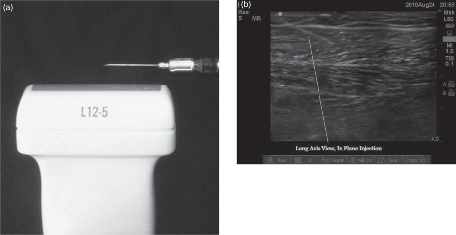
Fig. 7.2 Ultrasound-guided procedure for the in-plane approach. (a) Needle inserted along the length of the transducer; (b) In-plane view of needle path (white line).
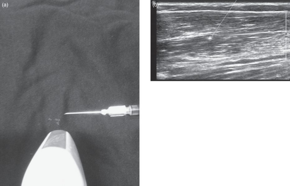
Fig. 7.3 Ultrasound-guided procedure for the out-of-plane approach. (a) Injection technique across the short access of the transducer; (b) Needle viewed as hyperechoic dot.
Fig. 7.4 Out-of-plane approach with needle tip incorrectly positioned out of the ultrasound beam and, therefore, potentially in an untargeted structure.
In addition to providing direct assessment about the depth/location of the target and the needle, US also provides information about the volume of injectate and resulting distention of the muscle as the injection is performed. This added information can guide the clinician during the procedure to avoid injection of excess volume at one injection site.
Commonly targeted muscles
Anterior neck muscles
- Sternocleidomastoid.
The superficially located sternocleidomastoid can be imaged either in longitudinal or in transverse plane (Fig. 7.5). The transverse plane often provides a better assessment of the fascial planes between muscles, as well as the location of adjacent vascular structures (Fig. 7.6). Therefore, a scout scan should include scanning in both planes. The clinician can then choose a scanning plane which provides the best view of the sternocleidomastoid, carotid and jugular vessels. The sternocleidomastoid can be approached with either an in-plane or out-of-plane needle insertion. Injections are most often performed in the upper one-third or proximal portion of the muscle to reduce the risk of dysphagia (Truong et al., 1989).
- Longus colli and capitus.
These muscles are located deep in the anterior cervical region. Without image guidance, these muscles are extremely challenging to target. Combined EMG guidance with US, fluoroscopy or CT is generally recommended. With US guidance, Doppler imaging should be employed as this will provide visualization of the carotid and internal and external jugular veins (Fig. 7.7). Longitudinal and transverse scans should be performed to determine which view provides the optimal view of the target as well as the structures to be avoided.
- Scalene complex.
The scalene muscles (anterior, middle, posterior) are located in the anterior triangle of the neck, lateral, posterior and deep to the adjacent sternocleidomastoid. When performing US-guided scalene injections, a transverse view of the muscle usually provides the best view of the fascial planes between the sternocleidomastoid, scalene muscles, vessels and nerves (Fig. 7.8). In the transverse view, the roots/trunks of the brachial plexus are easily distinguished as they descend through the neck, running between the anterior and middle scalene. Doppler imaging will confirm that these circular hypoechoic structures have no flow and are nerves, not vessels (Fig. 7.8c).
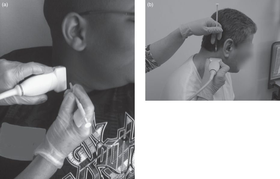
Fig. 7.5 Out-of-plane injection of the sternocleidomastoid muscle. (a) Longitudinal view; (b) transverse view.
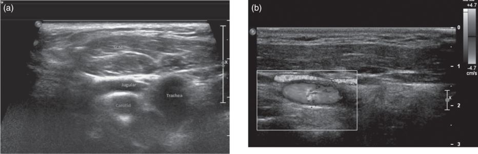
Fig. 7.6 Sternocleidomastoid muscle by ultrasound. (a) Transverse B-mode; (b) longitudinal color Doppler image.
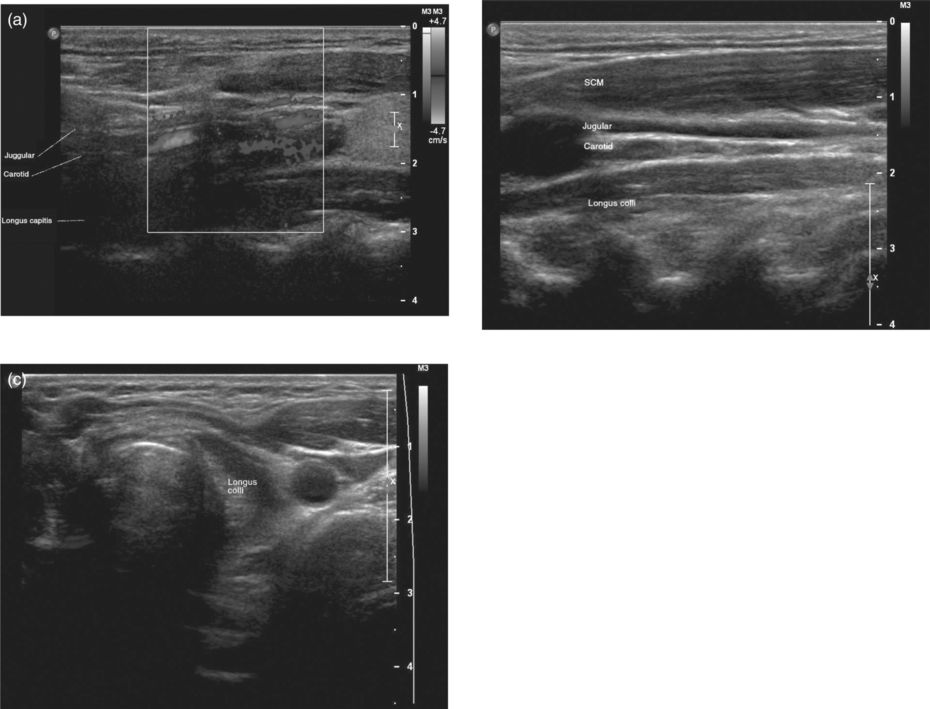
Fig. 7.7 Longus colli and capitis by ultrasound. (a) Longitudinal Doppler; (b) longitudinal B-mode; (c) transverse B-mode.
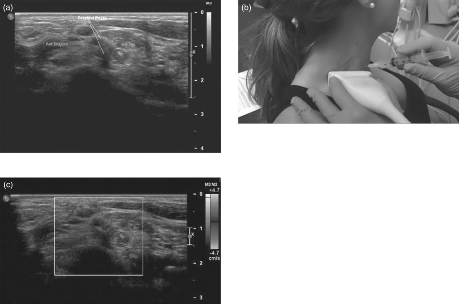
Fig. 7.8 Scalene muscles. (a) The brachial plexus can be distinguished from the scalene muscles by transverse B-mode ultrasound. (b) Clinical image showing the transverse scan for out-of-plane injection of the scalene muscles. (c) The brachial plexus and scalene muscles in transverse Doppler image.
Stay updated, free articles. Join our Telegram channel

Full access? Get Clinical Tree


