, here D T is the thermal diffusivity of the tissue (a constant with a typical value for most tissues of ~1.4 × 10⁻³ cm2/s) and t p is the laser pulse duration. Hence, the thermal confinement condition can be written as follows: δ T < L p. For example, a laser pulse duration of t p = 0.5 μs (a relatively long laser pulse) will result in δ T = 0.5 μm. This can easily be achieved, as the spatial resolution of most photoacoustic tomography (PAT) systems is typically much larger than 0.5 μm.

Fig. 29.1
Thermal confinement
29.2.2 Stress Confinement Condition
Similarly to the thermal confinement condition, the stress confinement condition requires that over the course of the light excitation pulse, photoacoustic waves produced by the object should not travel longer than the size of the object (Fig. 29.2). Over the course of one pulse duration, photoacoustic waves travel a distance of t p c (c = 1.54 mm/μs in soft tissues). Hence, the stress confinement condition requires that t p c < L p . For example, for a laser pulse duration of t p = 0.5 μs, the photoacoustic waves travel t p c = 770 μm, which greatly smears the spatial resolution of most photoacoustic systems. To allow a spatial resolution of 150 μm (i.e., L p = 150 μm), the laser pulse duration t p must be no more than 97 ns. As can be seen, it is much harder to satisfy the stress confinement than the thermal confinement.
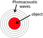

Fig. 29.2
Stress confinement
29.3 Photoacoustic Tomography
PAT has rapidly developed over the past two decades into a powerful imaging modality that provides high tissue depth of penetration while maintaining high spatial and temporal resolutions. It has found a diverse range of applications in oncology [3], ophthalmology [4], endoscopy [5], dermatology [6], cardiology [7], and neurology [8]. Based on the photoacoustic effect, the principle of PAT is the conversion of pulsed light into ultrasound waves by absorbing molecules in a tissue and the detection of these ultrasound waves using an ultrasound transducer(s) to form an image. In photoacoustic tomography, a tissue will be illuminated by a broad diffuse laser pulse. The pulse energy will propagate through the tissue as it is scattered and absorbed by chromophores in the tissue. The absorbed photons are converted into heat, leading to a local transient temperature rise. This increase in temperature generates a local pressure rise, according to the thermoelastic expansion. The pressure propagates as an ultrasound wave until it gets to the surface of the tissue. An ultrasound transducer or an array of transducers is measuring a time trace of the ultrasound waves as they reach the surface of the tissue. The traces are then reconstructed into a full three-dimensional photoacoustic image that represents the origin of the photoacoustic waves. Various reconstruction algorithms were devised for various photoacoustic system geometries and are the topic of other reviews [9]. The photoacoustic signal is proportional to the product of the object absorption coefficient and the fluence of light reaching this object, which represents the absorbed energy density by the object. Because the absorption and scattering of ultrasound waves by a tissue are relatively minimal, PAT provides high tissue depth of penetration as well as a high spatial resolution. Finally, unlike in ultrasound imaging, PAT exhibits minimal speckle artifacts. This is because the ultrasound waves forming the image propagate in one direction (from the tissue to the transducer) and therefore do not have an opportunity to coherently interfere with each other.
29.3.1 Intrinsic Contrasts
A number of chromophores are endogenously expressed by different tissues. Of particular relevance are the chromophores which are highly abundant and exhibit an absorption profile in the visible or near-infrared range. Such molecules include hemoglobin, melanin, water, fats, and certain proteins (Fig. 29.3). Since in most tissues hemoglobin absorption dominates most other endogenous chromophores, a photoacoustic image of a tissue would primarily show the distribution of blood within the tissue. Hemoglobin at different oxygen saturation levels will display different absorption spectra. This difference in optical absorption between oxygenated and deoxygenated hemoglobin can be exploited to map the blood oxygenation levels within a tissue, by acquiring multiple photoacoustic imaging at different wavelengths and quantifying the spectra of each pixel in the image using a spectral component analysis algorithm [10]. Melanin is also a major absorber in tissues such as skin and the retinal pigment epithelium (RPE) in the eye. In those tissues, melanin will be the main contributor for the photoacoustic signal at the visible and near-infrared wavelengths. Applications of photoacoustic imaging of melanin include visualizing melanoma tumors in the skin [11] and imaging the retina [4, 12]. Finally, morphological changes in a tissue, such as those occurred during a thermal burn, can cause changes in the optical absorption of the skin that outlines the physical extent of the burn and may help in classifying burns based on their depth [13].
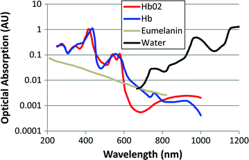

Fig. 29.3
Optical absorption spectra of the common endogenous absorbers in tissues. Deoxygenated and oxygenated hemoglobin (Hb and HbO 2 , blue and red, respectively; http://omlc.ogi.edu/spectra/hemoglobin/summary.html), melanin (Eumelanin, gray; http://omlc.ogi.edu/spectra/melanin/), and water [84] (black; http://omlc.ogi.edu/spectra/water/data/kou93b.dat) in arbitrary units. The final absorption coefficient of a tissue will constitute some linear combination of these components, where the relative weights will vary across tissues
29.3.2 PAT Imaging Configurations
There are largely two categories for PAT setups, a first using diffuse light and an unfocused transducer array and a second using diffuse light and a focused transducer. The second implementation is also referred to as acoustic-resolution photoacoustic microscopy (AR-PAM) and should not be confused with optical-resolution photoacoustic microscopy (OR-PAM), where light is also tightly focused with a lens, thereby providing optical resolution in the lateral plane of the image. Previous reviews have covered in detail the various PAT setups [14, 15]. Here, we briefly review some of the common PAT setups at the context of the applications to which they are best suited for.
29.3.2.1 Spherical Scanners
Since the photoacoustic waves that are formed by an optically absorbing object travel in all directions, the ultimate tomography system would provide a good coverage of the tissue surface where ultrasound waves can be measured. Ultrasound detectors arranged in a half sphere would therefore provide a near ideal arrangement for imaging the breast [16], as depicted in Fig. 29.4. The excitation light in this system is delivered through a fiber that is attached to an Nd:YAG laser source that is further converted using an optical parametric oscillator (OPO) to any wavelength of choice in the near infrared at a pulse repetition rate of 10 Hz. The ultrasound array is composed of 128 individual unfocused transducers with a center frequency of 5 MHz arranged in a sparse spiral patterns on a bowl. To further improve the spatial coverage of the tissue surface, the ultrasound array is incrementally rotating so by the end of the acquisition, most of the tissue surface has been sampled. This provides an isotropic spatial resolution of ~250 μm across a 5-cm-diameter field of view. Since all 128 ultrasound transducers are sampled simultaneously, a photoacoustic image made from 240 rotational positions can be acquired in 24 s. In addition to imaging the breast, this system has been used for whole-body small animal imaging [17] (Fig. 29.4c). Another implementation of a spherical scanner is through a linear ultrasound array arranged as an arc that is rotating about an object [18, 19]. Whatever the arrangement of transducers is, the common reconstruction method for spherical scanners is the spherical back projection algorithm [9]. However, it is possible to incorporate some prior knowledge on the structures and elements that make up the tissue to form an even higher-quality photoacoustic image using wavelet filtering [19]. This allowed the system to generate detailed images of a mouse abdomen (Fig. 29.5). The arc array is made of 64 transducer elements at a center frequency of 3.1 MHz. Over a 360° rotation, this covers nearly a perfect sphere for an accurate reconstruction, resulting in an isotropic 0.5 mm spatial resolution. To achieve high signal-to-noise ratio, each ultrasound measurement is taken by averaging the response from 32 laser pulses. This greatly compromises the temporal resolution of the system, which was 8 min per three-dimensional image of a whole mouse.
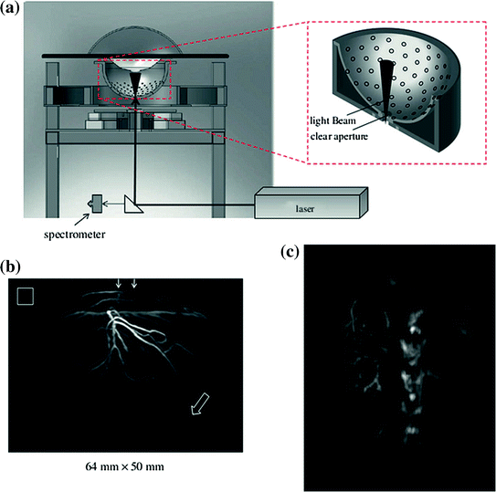
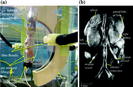

Fig. 29.4
Hemispherical photoacoustic tomography breast scanner. a Schematic of system. b Maximum intensity projection of the left breast of a healthy individual taken at an excitation wavelength of 800 nm. Arrows at the top represent the direction of the excitation light illumination, and the hollow arrow shows the position of a blood vessel at a depth of 40 mm. Hollow box is 1 × 1 cm in size. c Maximum intensity projection photoacoustic image of the abdominal section of a mouse. Note the clear vasculature detail evident in the kidney. Recreated with kind permission from American Association of Physicists in Medicine and SPIE [16, 17]

Fig. 29.5
Whole-body small animal photoacoustic tomography spherical scanner. a An arc-shaped ultrasound array made with 64 elements that rotate 360° around the animal. b Three-dimensional rendering of a photoacoustic image of a nude mouse. Several anatomical structures can be clearly seen including the kidneys and spleen. Recreated with kind permission from SPIE [19]
29.3.2.2 Cylindrical Scanners
Similarly to spherical PAT scanners, in cylindrical scanners, photoacoustic waves are measured across the surface of a cylinder that surrounds the object. This has been implemented either using a single-element transducer that rotates around the object [20], or using an ultrasound transducer array arranged in a circle [21]. The single-element transducer implementation is particularly popular among the cylindrical scanners, primarily for its simplicity and low cost. Figure 29.6 shows the implementation of such cylindrical system, comprising a 3.5 MHz transducer focused on the elevation (z) axis. The illumination and the object are not moving during the scan, while the transducer is rotating around the object in circles. The object is illuminated from the top using an Nd:YAG laser of 532 nm at a safe laser energy density of less than 10 mJ/cm2. This resulted in a system with 200 μm spatial resolution. Such cylindrical scanners have found applications in monitoring tumor growth [22], early detection of arthritis [23], and monitoring brain hemodynamics [24].


Fig. 29.6
Cylindrical photoacoustic tomography scanner. a A semi-focused transducer rotated around the animal head and a jack moved the animal up and down to allow for a full cylindrical coverage of the animal brain. b Non-invasive photoacoustic image of the superficial layer of a rat brain acquired with the skin and skull intact. Optical absorption shown in gray scale (darker areas indicate greater absorption). C cerebellum; H cerebral hemispheres; O olfactory bulbs; MCA middle cerebral artery; CS cruciate sulcus; FT fissura transversa; V blood vessels. Total image size is 4 × 4 cm in lateral dimension. The blood vessels distributed in the superficial layer of the cerebrum and the cerebellum are clearly visible with high optical contrast and accurate localization. c Open skull photograph of the rat brain surface acquired after the photoacoustic experiment. Recreated with kind permission from Nature Publishing Group [8]
29.3.2.3 Planar Scanners
In tissues such as skin or tissues containing bone structures, acquiring the large angular aperture needed for spherical and cylindrical scanners is not feasible. In such cases, acquiring photoacoustic signals over a flat surface with a planar scanner is preferable. Planar scanners can be implemented either as a single transducer that is raster scanning the surface in two-dimensions, a one-dimensional ultrasound array that scans the surface in the other direction [25], or a two-dimensional ultrasound arrays [26, 27]. The main trade-off between these options is speed, cost, and ease of use. Most planar scanners have been implemented as one-dimensional array systems that are assembled into a handheld device. Such systems also have the capability to acquire ultrasound images in addition to photoacoustic images (some photoacoustic scanners were even adapted from an ultrasound scanner) so to allow the coregistered acquisition of an ultrasound and a photoacoustic image [28, 29]. While the ultrasound image provides anatomical information, the photoacoustic image provides physiological and possibly molecular information (if molecular agents are used). Planar scanners typically suffer from image artifacts and lower lateral resolution due to their limited aperture compared to the spherical and cylindrical counterparts.
Recently, a planar photoacoustic scanner capable of producing real-time photoacoustic images at 50 frames per second has been devised [30, 31]. The scanner is made of 48 elements with a central frequency of 30 MHz to allow for high spatial resolution across the first 3 mm of the tissue (Fig. 29.7). By rapidly scanning the array, a full volumetric frame rate of 1 frames per second can be achieved for 166 B-scans volume. Other similar scanners with larger number of elements have been devised as well [32], including a 64-element 7.5 MHz linear array that provides a frame rate of 7.5 frames per second [29] and used to visualize blood vessels at a depth of 10 mm in the leg. Another planar scanner system has employed a commercial ultrasound system with 128 elements operating at 5 MHz was used to image the vascular bed in the human arm [33].
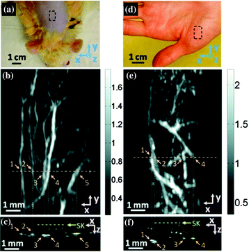

Fig. 29.7
Planar photoacoustic scanner. a Photograph of a Sprague–Dawley rat with hair removed before photoacoustic imaging, where x represents the beam forming (B-scan) direction, y represents the mechanical scanning direction, and z represents the depth direction. The dashed rectangle indicates the imaged area. b Photoacoustic maximum amplitude projection (MAP) image of the rat. The gray scale represents relative optical absorption. c Photoacoustic B-scan image corresponding to the dashed horizontal line in (b), showing the depths of the blood vessels: SK skin surface. Numbers 1–5 indicate corresponding blood vessels in (b) and (c). d Photograph of a human hand. The dashed rectangle indicates the imaged area. e Photoacoustic MAP image of the hand. f Photoacoustic B-scan image corresponding to the dashed horizontal line in (e). Numbers 1–4 indicate corresponding blood vessels in (e) and (f). Recreated with kind permission from SPIE [30]
Another implementation of a planar scanner is based on an all-optical ultrasound sensor (Fig. 29.8a). The sensor is essentially a transparent Fabry–Perot film etalon, where a thin polymer spacer is sandwiched in between two reflectors [34, 35]. When an acoustic wave hits the etalon, it slightly modifies the spacer thickness, which locally and temporally affects the optical reflection conditions of the etalon. By scanning the etalon surface with a coherent laser beam, an effective two-dimensional ultrasound array results. This approach has numerous advantages over conventional ultrasound arrays, including low cost, simplicity, ability to transmit the exciting laser pulse through the etalon, and an ultrawide frequency bandwidth from 100 kHz to 22 MHz. Moreover, this approach allows for a fine spatial sampling of the etalon, where the only limit to the ultrasound element size is the diffraction limit of the sampling laser beam on the etalon surface. This allows for element sizes as small as tens of micrometers without loss of sensitivity. The challenge with such systems is the sequential reading of the etalon, which limits their speed, although this limitation can be overcome by either using higher repetition rate lasers or employing multiple optical beams to sample the etalon simultaneously [36]. This system was used to image a variety of tissues, including a human hand (Fig. 29.8b) and subcutaneous tumors that were implanted in mice [37] and in the mouse brain [38].
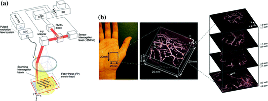

Fig. 29.8
All-optical photoacoustic planar scanner. a The Fabry–Perot (FP) sensor head is placed in acoustic contact with the surface of the skin. Nanosecond excitation laser pulses emitted by a tuneable OPO laser system are directed onto the sensor head and transmitted through it into the underlying tissue, thereby exciting acoustic waves. A second laser operating at 1,550 nm provides a focused sensor interrogation laser beam that is raster scanned over the surface of the sensor to map the distribution of the photoacoustic waves arriving at the sensor head. From the 2D distribution of the photoacoustic waves, a 3D image is then reconstructed. b In vivo photoacoustic image of the vasculature in the palm using an excitation wavelength of 670 nm. Left photograph of the imaged region, middle volume-rendered image, right lateral slices at different depths. The arrow ‘A’ indicates the deepest visible vessel, which is located 4 mm beneath the surface of the skin. Recreated with kind permission from IOP Publishing [37]
29.3.2.4 Acoustic-Resolution Photoacoustic Microscopy
AR-PAM systems typically employ a single-element-focused transducer that is raster scanning the tissue. Similarly to conventional ultrasound systems, the scanner acquires individual vertical line scans (A-scans) and combining consecutive A-scans into a two-dimensional B-scan image or a three-dimensional volumetric image. These systems are typically slower than array systems due to the sequential scanning nature. However, they are less vulnerable to motion artifacts or acoustically scattering objects such as bones, as every A-scan is reconstructed independently of its neighboring A-scans. In most AR-PAM scanners, light is weakly focused as a spot or a hollow ring on the tissue below the transducer. This can be done either with a conical lens [39] or with a fiber-optic ring [40, 41]. Figure 29.9 shows a common implementation of an acoustic-resolution photoacoustic microscope scanner and its application in imaging the blood vessels in a human hand [39]. In addition to visualizing blood vessels in a tissue, such photoacoustic systems were used to assess the oxygen saturation level of the blood vessels (Fig. 29.10). This is done by acquiring photoacoustic images of a tissue at multiple excitation wavelengths and fitting the known spectra of oxygenated hemoglobin and deoxygenated hemoglobin to the acquired photoacoustic response. Once the relative amplitudes of the oxygenated and deoxygenated hemoglobin signals have been isolated, oxygen saturation levels can be easily calculated as HbO2/(HbO2 + Hb). Another application of acoustic-resolution photoacoustic microscopy has been ocular imaging (Fig. 29.11). While the spatial resolution may be lower than other retina imaging methods such as optical coherence tomography, the depth of penetration provided by photoacoustic imaging allows visualizing the entire ocular globe. The image was acquired at 740 nm wavelength with a 25 MHz transducer and consisted of 48 by 32 A-scans combined into one volumetric image spanning 12 × 8 mm lateral scan area (250 μm lateral step size). With the 25 MHz focused transducer, the system provides a spatial resolution of 50 μm (axial) and 240 μm (lateral), which allowed visualizing the major blood vessels of the retina and the choroid as well as other pigmented structures in the eyes of non-albino animals [4].
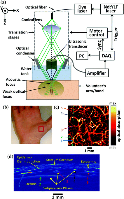

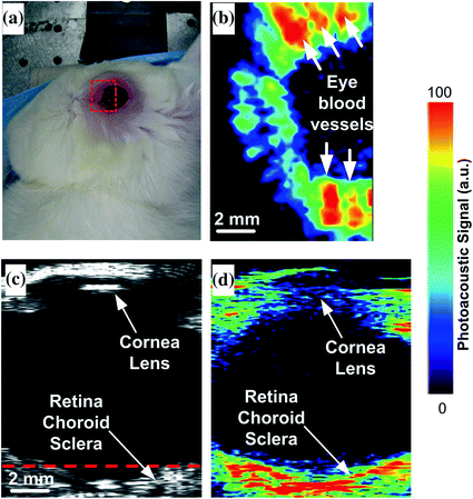

Fig. 29.9
Acoustic-resolution photoacoustic microscopy scanner. a Schematic of the photoacoustic microscope used in the described experiments. b Photograph of the palm of the volunteer. The red box indicates the imaged area 8 × 8 mm. c B-scan PA image taken along the dashed line in (d). Notable features including the stratum corneum, epidermal–dermal junction, and subpapillary blood vessels, are all labeled. Selected vessels have been labeled with color arrows for reference with the image in (d). d Maximum amplitude projection PA image taken from the palm using a 584-nm laser excitation wavelength. The green dashed line indicates the cross section shown in (c). Recreated with kind permission from SPIE [39]

Fig. 29.10
Photoacoustic imaging of blood oxygen saturation levels. Four wavelengths (578, 584, 590, and 596 nm) were employed to acquire four photoacoustic images. a Structural image acquired at 584 nm. b Vessel-by-vessel sO2 mapping based on a least squares fitting of the four images. The calculated sO2 values are shown in the color bar. Recreated with kind permission from Nature Publishing Group [3]

Fig. 29.11
Photoacoustic ocular imaging. a Photograph of the rabbit eye. b Horizontal photoacoustic, c vertical ultrasound, and d vertical photoacoustic images of the eye of the live rabbit. The area of the eye imaged in (b) is outlined by the red boundary (dotted box) in (a), and the depth is noted by the dashed red line in (c). Recreated with kind permission from the Optical Society [4]
29.4 Optical-Resolution Photoacoustic Microscopy
If the target tissue is superficial or optically clear, it is possible to generate photoacoustic images at a spatial resolution superior to what acoustic transducers may allow. This is done by focusing the excitation light beam onto the tissue of interest, such that the spatial lateral localization is provided by the optical beam, while the axial localization is provided by the ultrasound transducer. This leads to anisotropic spatial resolution, high lateral resolution, and lower axial resolution. Nonetheless, this approach has found many important niche applications, including ocular imaging [12, 42, 43], microvessels imaging [44, 45], and oximetry [46].
29.4.1 System Configurations
A variety of optical-resolution photoacoustic scanners have been constructed. Because the spatial localization of this technique is dependent on optical confinement, the depth of penetration is limited to not more than 1 mm in optically scattering tissues. An important distinguishing feature between AR-PAM and OR-PAM is that in AR-PAM, the acoustic transducer needs to physically move to allow the raster scan to take place, whereas in OR-PAM, only the optical beam needs to move. This has major ramifications on the scan speed as optical beams can be steered ultrafast using galvo mirrors (Fig. 29.12a). Moreover, because the laser excitation spot size in OR-PAM is significantly smaller than that in AR-PAM, the total energy per pulse should be significantly reduced to stay below the 20 mJ/cm2 pulse energy density limit set by American National Standards Institute (ANSI) [47]. This allows the use of pulsed laser diodes, which are significantly cheaper than the traditional Nd:YAG lasers that are typically used in photoacoustic imaging. However, using lower pulse energies reduces the total signal and therefore limits the sensitivity of the system.
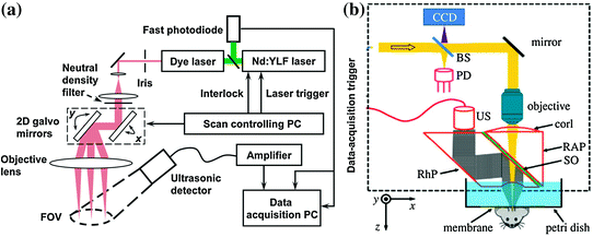

Fig. 29.12
Optical-resolution photoacoustic microscopy (OR-PAM) scanners. a An OR-PAM system implemented with a 2D galvo mirrors for ultrafast raster scanning of a tissue. A static unfocused ultrasound transducer is positioned at an angle to the excitation beam path. b A scanning head OR-PAM scanner is implemented with the head being physically moved across an object to form a three-dimensional photoacoustic image. BS beam splitter; PD photodiode; CorL correction lens; RAP right-angled prism; SO silicone oil; RhP rhomboid prism; US ultrasonic transducer (50 MHz). The CCD is used to view the imaging region. The components that lie within the dotted rectangle form the scan head, which is mechanically translated in order to acquire an image. Recreated with kind permission from The Royal Society and the Optical Society [15, 44, 85]
Another common implementation of OR-PAM is shown in Fig. 29.12b. A high numerical aperture lens is focusing the excitation light to the surface of a tissue. Acoustic waves that return from the tissue propagate through an acoustic lens that collimate the wave, reflected off an optically transparent acoustical mirror, and detected by an unfocused transducer. The entire scanning head is raster scanning a two-dimensional surface by being moved mechanically and acquiring an A-scan at each position, resulting in a three-dimensional photoacoustic image.
29.4.2 Applications of OR-PAM
The high spatial resolution offered by OR-PAM can produce en-face images of the target tissue. En-face images of blood vessel capillaries [45] as well as individual red blood cells [44] have been demonstrated (Fig. 29.13a, b). Moreover, by acquiring several OR-PAM images at multiple wavelengths, OR-PAM can be used to create an oxygen saturation map of the ear (Fig. 29.13b). Note that while the lateral spatial resolution is approximately 2.5 μm, the axial resolution is approximately 10 μm. The ability to calculate oxygen saturation levels has recently been applied for the dynamic imaging of individual red blood cells in vivo. Figure 29.13d shows the dynamic transition of an individual red blood cell in a capillary of a living mouse brain [46]. The dynamic images monitor the oxygen capacity of the individual red blood cell as it is traveling through the capillary vessel. In addition to visualizing blood vessels in skin applications, OR-PAM has shown great promise for ocular imaging, primarily because of the optical clarity of the eye. Imaging of both the retina [12, 48] and the iris [42] has been demonstrated by different groups using OR-PAM. Importantly, despite the retina being ~8 mm or 25 mm under the cornea in mice and human, respectively, the clarity of the cornea, lens, and vitreous gel of the eye allows OR-PAM to focus the light onto the retina and achieve high lateral resolution photoacoustic images. In fact, OR-PAM of the retina is using the focusing capability of the animal lens to focus the light onto the retina, so in theory, no additional optical lens is required. The contrasts provided by the eye are primarily hemoglobin and melanin. The RPE is a highly pigmented layer located between the retina and the choroid and exhibits a high scattering and absorption coefficient. Hence, OR-PAM can clearly visualize the RPE but not the choroid structures under it.
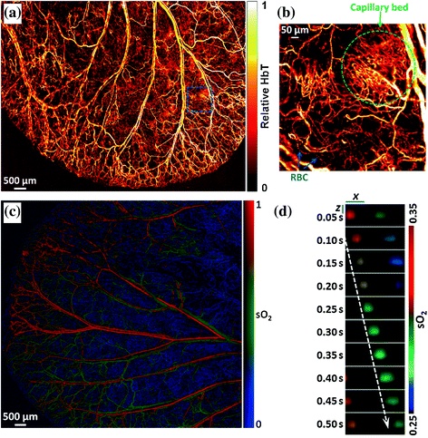

Fig. 29.13
OR-PAM images of capillaries. a OR-PAM of total hemoglobin (HbT) in a living mouse ear, revealing the vascular anatomy. b Inset shows a densely packed capillary bed and individual red blood cells traveling along a capillary. c Dual-wavelength (561 and 570 nm) OR-PAM calculation of blood oxygen saturation levels (sO2) in a living mouse ear. d Sequential snapshots of single RBCs releasing oxygen in a mouse brain. Scale bars: x = 10 µm, z = 30 µm. Blood flows from left to right. The dashed arrow follows the trajectory of a single flowing RBC. Recreated with kind permission from the Optical Society and the National Academy of Sciences [44, 46]
29.5 Photoacoustic Molecular Imaging
Photoacoustic imaging scanners has been optimized over the past two decades to provide superb imaging performance of the endogenous pigments in tissues, primarily hemoglobin and melanin. However, most biomolecules are transparent in the visible and near-infrared range and hence will not provide a photoacoustic contrast. Therefore, to allow photoacoustic imaging to reach its full potential, exogenous imaging agents should be used. Such imaging agents can be either molecularly targeted to a given biomolecule or non-targeted. A wide variety of photoacoustic contrast-producing agents (aka, contrast agents) have been demonstrated, including small-molecule optical dyes, organic and metallic nanoparticles [49]. By conjugating these contrast agents to targeting moieties such as antibodies [50] or peptides [41], they can be targeted to a specific biomolecule of interest, providing it with an observable photoacoustic signal. Another common targeting mechanism is leveraging biological activities that can that leads to the accumulation of the agents in the target tissue, such as the enhanced retention and permeation effect (EPR) of tumors [51]. The following sections discuss the design requirements of photoacoustic contrast agents, the process needed to validate them in vivo, and the diverse range of applications they are applied to.
29.5.1 Design of Photoacoustic Imaging Agents
Simply put, a good photoacoustic imaging agent should produce as high signal as possible, accumulate in high levels in the target tissue and as minimally as possible in non-target tissues, and be non-toxic. To maximize the photoacoustic signal of a particle, it is not enough to have a high absorption cross section. Indeed, the absorbed energy should be converted into heat, and not, for example, to fluorescent light. In addition, it is preferred that the imaging agent will circulate in the blood stream just long enough to accumulate in the target tissue, but not too long that it produces a non-specific signal when the tissue is being imaged. If the imaging agent is molecularly targeted to a specific biomolecule of interest, the affinity between the agent and the target should be strong enough so the agent is rapidly accumulating in the target region and does not fall off, but yet specific enough so it does not bind to similar biomolecules in the tissue. Finally, the imaging agent should be well tolerable by a living subject with no adverse toxic effects. Often the toxicity of an agent is a function of dose. Since the photoacoustic signal of an agent will determine the dose needed to visualize the target tissue, the photoacoustic signal of an agent is closely related to the potential toxicity of the agent. Below we outline several additional conditions that affect the photoacoustic signal of an agent and discuss the experiments needed to validate a photoacoustic agent.
Stay updated, free articles. Join our Telegram channel

Full access? Get Clinical Tree


