Hemodialysis Apparatus
Suhail Ahmad
Madhukar Misra
Nicholas Hoenich
John T. Daugirdas
Hemodialysis (HD) apparatus can be broadly divided into a blood circuit and a dialysis solution circuit, which meet at the dialyzer. The blood circuit begins at the vascular access. From there blood is pumped through an “arterial blood line” to the dialyzer. Blood is returned from the dialyzer to the patient via a “venous blood line.” These terms are used even though often only venous blood is being accessed (such as when using a venous catheter). More precise would be to term these the “inflow” blood line and “outflow” blood line, but as often is the case, the traditional names rather than more correct terms continue to be used. Various chambers, side ports, and monitors are attached to the inflow and outflow blood lines, and are used to infuse saline or heparin, to measure pressures and to detect any entrance of air. The dialysis solution circuit includes the dialysis solution (dialysate) supply system, which makes dialysate online by mixing purified water with concentrated dialysate solutions. The final dialysate is then pumped through the dialysate compartment of the dialyzer, the latter being separated from blood compartment by a semi-permeable membrane. The dialysis solution circuit includes various monitors that make sure that the dialysis solution is at the right temperature and has a safe concentration of dissolved components. Also, a blood leak detector is present with the purpose of stopping dialysis if blood products are detected in the outflow dialysate.
I. BLOOD CIRCUIT. The inflow (arterial) blood line connects the vascular access to the dialyzer, and the outflow (venous) blood line runs from the dialyzer back to the vascular access. Blood is moved through the dialyzer by a pump, usually a spring-loaded roller pump. The roller moves blood through the blood tubing by completely occluding a small segment of the tubing then rolling the occluded segment forward (like milking a straw).
A. Inflow blood line: Prepump segment. The prepump segment is the part of the blood line which links the patient’s access to the blood pump. This segment contains a sampling port, a saline infusion line, and, on some lines, a “prepump” pressure monitor (see P1 in Fig. 4.1).
The sampling port is used to sample blood from the line and is the point from which predialysis and postdialysis blood
is usually taken. The saline infusion “T” line is used to prime the dialyzer circuit, and also to rinse-back the contents of the blood compartment at the end of dialysis. Because all three of these elements (sampling port, monitor, and saline “T”) are located in the negative pressure portion of the blood line, if a connection is broken here, air can quickly enter the blood line. In the event of an incomplete connection, microbubbles can be introduced, which can get trapped in the hollow fibers of the dialyzer, which reduces the efficiency of dialysis, and can even lead to clotting of the circuit.
is usually taken. The saline infusion “T” line is used to prime the dialyzer circuit, and also to rinse-back the contents of the blood compartment at the end of dialysis. Because all three of these elements (sampling port, monitor, and saline “T”) are located in the negative pressure portion of the blood line, if a connection is broken here, air can quickly enter the blood line. In the event of an incomplete connection, microbubbles can be introduced, which can get trapped in the hollow fibers of the dialyzer, which reduces the efficiency of dialysis, and can even lead to clotting of the circuit.
It is advisable to use blood lines with a prepump pressure monitor (P1), although not all blood lines have this. The pressure monitor is linked via a small tubing attached at a right angle to the blood line. This small tubing is kept filled with air, and the other end is attached to an air chamber that communicates through a filter to a pressure transducer. Because the blood pump is demanding blood at a fairly fast rate (200-600 mL/min) and because of the resistance to flow at the “arterial” opening of the vascular access catheter or “arterial” needle, the pressure in the segment of the “arterial” line between the vascular access and the blood pump is negative (below zero), and often substantially so. How negative, is a function of the blood flow rate, the blood viscosity (which increases with hematocrit), the size of the inflow catheter lumen or needle, and whether or not the end of the arterial needle or catheter is partially obstructed by nearby tissue from the inside wall of the vascular access.
For safety, the pressure limits of the P1 monitor are set above and below the usual normal working range for the patient. This is generally performed automatically, and the range above and below the prevailing pressure is machine dependent. If the
pressure goes out of range, an audible alarm will sound and the blood pump stops. For example, the prepump pressure monitor might be set to alarm if the pressure rises above -50 or falls below -200 mm Hg. On the low (-50) side, the pressure limit alarm might be triggered by a line separation (accidental disconnection of the blood tubing from the venous catheter or arterial needle). In such a case, after the line separates, the resistance to inflow will be suddenly reduced, and the negative pressure may rise above -50 mm Hg, triggering the alarm. However, this pressure alarm should never be relied upon to detect a line separation, as the pressure may remain in range, even after a line separation. For example, if there is a partial blockage in the inflow line after line separation, or if an arterial needle pulls out from the access, continued resistance to inflow by the needle may keep pressure in the set range; then the alarm may not sound, and the blood pump will keep on pumping air into the circuit. The other use for the prepump pressure alarm is on the “high” side: if there is obstruction to blood flow either by a kink in the line or by a clot at the access needle lumen, the arterial pressure may become more negative than the set limit (e.g., -250 mm Hg); then the alarm will be activated and the blood pump will stop, giving the care provider the opportunity to investigate the source of the problem.
pressure goes out of range, an audible alarm will sound and the blood pump stops. For example, the prepump pressure monitor might be set to alarm if the pressure rises above -50 or falls below -200 mm Hg. On the low (-50) side, the pressure limit alarm might be triggered by a line separation (accidental disconnection of the blood tubing from the venous catheter or arterial needle). In such a case, after the line separates, the resistance to inflow will be suddenly reduced, and the negative pressure may rise above -50 mm Hg, triggering the alarm. However, this pressure alarm should never be relied upon to detect a line separation, as the pressure may remain in range, even after a line separation. For example, if there is a partial blockage in the inflow line after line separation, or if an arterial needle pulls out from the access, continued resistance to inflow by the needle may keep pressure in the set range; then the alarm may not sound, and the blood pump will keep on pumping air into the circuit. The other use for the prepump pressure alarm is on the “high” side: if there is obstruction to blood flow either by a kink in the line or by a clot at the access needle lumen, the arterial pressure may become more negative than the set limit (e.g., -250 mm Hg); then the alarm will be activated and the blood pump will stop, giving the care provider the opportunity to investigate the source of the problem.
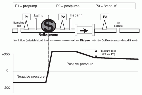 FIGURE 4.1 Pressure monitors (P1, P2, and P3) and pressures in blood circuit. |
B. Roller pump segment. The blood flow through the dialyzer is a function of the roller pump rotation rate and the diameter and the length of the blood line roller pump segment. In effect,
BFR = rpm (revolutions per minute) × roller pump segment volume (πr2 × length)
where BFR is the blood flow rate. The roller pump is generally self-occluding, that is, it adjusts to the dimension of the blood pump insert, to ensure that the full “stroke volume” is being delivered with each pass of the roller. With time, due to the repeated compression and relaxation of the pump insert with each passage of the rollers, the tubing can flatten. This reduces the “stroke volume” of the blood line and can reduce the effective blood flow rate. A similar effect may occur in the presence of a high (negative) inflow pressure. More rigid blood tubings have attempted to minimize this problem, and some machines have a built-in correction factor for the pump speed and the magnitude of negative pressure, a correction factor that one uses to correct blood flow rates.
C. Inflow (arterial) blood line: Postpump segment. This contains a “T” for heparin infusion, and also, in some lines, a small “T” connected to a postpump (P2 in Fig. 4.1) pressure monitor. The pressure reading in this segment is always positive (above atmospheric). The pressure at P2 can be combined with the reading at the venous pressure monitor, P3, to estimate the average pressure in the blood compartment of the dialyzer. In some machines, this, in combination with the pressure measured in the dialysis solution compartment, is used to
calculate how much ultrafiltration (UF) is taking place during dialysis. The pressure at the postpump monitor is normally quite high and depends on the blood flow rate, blood viscosity, and downstream resistance at the dialyzer and beyond. A sudden rise in the pressure at the P2 monitor is often a sign of impending clotting of the blood line and/or dialyzer. The heparin line is connected to a syringe containing heparin. The syringe is clamped into a mechanical device that slowly pushes on its plunger, delivering heparin at a constant rate during dialysis.
calculate how much ultrafiltration (UF) is taking place during dialysis. The pressure at the postpump monitor is normally quite high and depends on the blood flow rate, blood viscosity, and downstream resistance at the dialyzer and beyond. A sudden rise in the pressure at the P2 monitor is often a sign of impending clotting of the blood line and/or dialyzer. The heparin line is connected to a syringe containing heparin. The syringe is clamped into a mechanical device that slowly pushes on its plunger, delivering heparin at a constant rate during dialysis.
D. Outflow (venous) blood line: Air trap and pressure monitor. The out-flow blood line contains a venous “drip chamber” that allows for the collection and easy removal of any accumulated air from the line, a so-called “venous” pressure monitor (P3 in Fig. 4.1), and an air detector. The venous pressure can be used to monitor the state of coagulation. Incipient clotting of the blood circuit will usually first take place at the venous drip chamber, and clotting will cause a progressive rise in pressures at both P3 and P2. Venous pressure during dialysis is a function of blood flow rate, blood viscosity, and downstream access (needle or catheter) resistance. In patients with AV access, trends in venous pressure from dialysis to dialysis, measured at a standard, low blood flow rate, and corrected for patient’s blood pressure, height of the drip chamber and needle size, have been used to predict the occurrence of stenosis of the downstream vascular access (see Chapter 8). During dialysis, pressure cutoff limits in this venous (P3) monitor are also set around the usual operating pressures. If there is a sudden kink in the line, the pressure measured at P3 will suddenly shoot up over the preset limit and the blood pump will cut off. A sudden line disconnection may lower the pressure at P3 below the lower alarm cutoff limit, again shutting down the machine and limiting the extent of blood loss, but this by no means occurs all the time, especially when an AV fistula is used for access (Ribitsch, 2013) although a line separation from a venous catheter also may fail to trigger a venous pressure alarm, particularly when the operating venous pressure is relatively low. Again, with an AV access, if the venous needle is inadvertently pulled out from the access, this may not change the outflow pressure much, since most of the outflow resistance is in the venous needle. It is important to note that a venous pressure alarm CANNOT be relied upon to detect a venous line separation, and patients have exsanguinated due to continued operation of the blood pump when line separation went undetected (Axley, 2012; Ribitsch, 2013). For this reason, in patients who are at a high risk for line separation, such as those with cognitive defects, agitation, or those who repeatedly thwart staff efforts to leave their access site exposed, additional devices such as the Redsense sensor (Redsense Medical, Inc., Chicago, IL) can be used to detect blood leakage at the site of potential line separation. Attention must also be paid to effective taping of access needle insertion sites and
connections, and the site of the vascular access should always be exposed to caregivers’ view (Axley, 2012).
connections, and the site of the vascular access should always be exposed to caregivers’ view (Axley, 2012).
The venous air trap and detector are very important for patient safety. The chamber traps any air that may have entered the blood line before the blood is returned to the patient. Usually a level/air detector is placed around the top of the drip chamber; any increase in air (resulting in the drop of blood level) triggers an alarm. The power supply to the pump is then cut off and dialysis stops. An additional safety device is a powerful clamp below the drip chamber through which the blood tubing returning the blood to the patient passes, and which is activated by the presence of air in the blood tubing. When activated, the clamp snaps shut and blood pump is stopped; any air/blood mixture that may be present in the blood line is thereby prevented from passing back into the patient.
Despite the presence of an air detector, microbubbles can still pass to the patient. These microbubbles enter the circulation; however, their consequences are largely unknown. One strategy to limit microbubble formation is to maintain a high fluid level in the venous air chamber. The use of dialyzers that are provided by the manufacturer with fluid already filling the hollow fibers has also been shown to limit the release of microbubbles into the circulation during dialysis (Forsberg, 2013).
Additional practical information about the interpretation and use of pressure monitors during dialysis is given in Chapter 10.
II. DIALYSIS FLUID CIRCUIT. The dialysis fluid circuit contains a number of distinct components: (a) a stand-alone water purification system, (b) a proportionating system in which concentrates and treated water are mixed and delivered to the dialyzer, (c) monitors and alarms, (d) ultrafiltration control, and (e) advanced control options.
A. Water purification system. Patients are exposed to about 120-200 L of water during each dialysis treatment. All small-molecular-weight substances present in the water can pass across the dialyzer and enter the patient’s blood stream. For this reason, it is very important that the purity of the water used for dialysis be monitored and controlled. The Association for the Advancement of Medical Instrumentation (AAMI) has developed minimum standards for the purity of water used in hemodialysis. These and the methods of purifying water for dialysis are discussed in detail in Chapter 5.
B. Proportioning system. The basics of making dialysis solution are discussed in Chapter 5. Briefly, dialysis machines mix concentrated electrolyte solutions or powders with purified water to make a final dialysis solution that is delivered to the dialyzer. The final dialysis solution must be delivered at an appropriate temperature and it must be free of excessive dissolved air. This requires additional features, incorporating monitors and alarms.
Two types of proportioning systems exist: In the central delivery system, all of the dialysis solution used in the dialysis unit is produced by a single apparatus that mixes concentrates with purified water. The final dialysis solution is pumped through pipes to each dialysis machine. This approach offers the advantage of a lower initial equipment cost and reduced labor costs. However, it does not permit variations in the composition of dialysis solution for individual patients, and any error in the system exposes a large numbers of patients to complications arising from such errors. The second type is an individual system, in which each dialysis machine proportions its own dialysis solution concentrate with purified water.
C. Heating and degassing. Dialysis solution must be delivered to the dialyzer at the correct temperature (usually 35-38°C). Water obtained from a city water supply is below room temperature and must be heated; during heating, gases dissolved in the cold water expand and bubble out. The dialysis machine must remove this air from the water before use. Degassing is performed by exposing the heated water to a negative pressure.
D. Monitors and alarms. Several monitors and alarms are placed in the dialysis solution circuit to ensure safety.
1. Conductivity. If the proportioning system that dilutes the concentrates with water malfunctions, an excessively dilute or concentrated dialysis solution can be produced. Exposure of blood to a severely hyperosmolar dialysis solution can lead to hypernatremia and other electrolyte disturbances. Exposure to a severely hypoosmolar dialysis solution can result in rapid hemolysis and severe hyponatremia and hyperkalemia. Because the primary solutes in dialysis solution are electrolytes, the degree of their concentration in dialysis solution will be reflected by its electrical conductivity. A meter that continuously monitors dialysis fluid conductivity is incorporated in all proportionating systems. Conductivity is measured in terms of milliSiemens (mS) per centimeter (cm). One Siemen (S) is equal to the reciprocal of one ohm (an alternative term for a Siemen is “mho”). The normal conductivity range for dialysis solution is 12-16 mS/cm. If conductivity falls outside the preset limits, an alarm sounds and dialysate is prevented from proceeding to the dialyzer by a valve that diverts the dialysis solution to the drain. In such an event, the system “goes into bypass” protecting the patient and dialysis stops until the problem has been resolved. Causes of dialysis solution conductivity out of range include the following:
a. Empty concentrate container
b. Concentrate line connector not plugged in
c. Low water inlet pressure
d. Incorrect concentrate being used
e. Mixing chamber leakage
2. Temperature. Malfunction of the heating element in the dialysis machine can result in the production of excessively
cool or hot dialysis solution. Use of cool dialysis solution (down to 35°C) is not dangerous unless the patient is unconscious, in which case hypothermia can occur. A conscious patient will complain of feeling cold and shiver. On the other hand, use of a dialysis solution heated to >42°C can lead to blood protein denaturation and, ultimately, to hemolysis. The dialysis fluid circuit contains a temperature sensor, and if the temperature is outside the acceptable limits, the dialysis fluid is diverted to drain, as discussed earlier.
cool or hot dialysis solution. Use of cool dialysis solution (down to 35°C) is not dangerous unless the patient is unconscious, in which case hypothermia can occur. A conscious patient will complain of feeling cold and shiver. On the other hand, use of a dialysis solution heated to >42°C can lead to blood protein denaturation and, ultimately, to hemolysis. The dialysis fluid circuit contains a temperature sensor, and if the temperature is outside the acceptable limits, the dialysis fluid is diverted to drain, as discussed earlier.
3. Bypass valve. As mentioned previously, if either the dialysis solution conductivity or the temperature is out of limits, a bypass valve is activated to divert the dialysis solution around the dialyzer directly to the drain.
4. Blood leak detector. Small blood leaks will be invisible to the naked eye. A blood leak detector is placed in the dialysate outflow line (line containing dialysis fluid after it has passed through the dialyzer). If the detector senses blood, as occurs when a leak develops through the dialyzer membrane, the appropriate alarm is activated and the blood flow through the dialyzer is stopped automatically, to prevent potentially catastrophic blood loss.
5. Dialysate outflow pressure monitor. In machines that do not have special pumps and circuitry to control the UF rate directly, the pressure at this location can be used in conjunction with the pressure at the blood outflow line to calculate the dialyzer transmembrane pressure (TMP) and thereby estimate the UF rate.
E. Ultrafiltration control. With the use of high-flux/high-efficiency dialyzers it is necessary to have machines that can accurately control the UF rate throughout the treatment. There are several different methods in use and the hydraulics involved are complex and beyond the scope of this handbook. Precise UF control is a desirable feature for a dialysis machine to have and a manual approach to determine the UF rate by estimating the TMP is fraught with potential errors.
The most advanced method of UF control is a volumetric method. Such volumetric circuitry is incorporated into many currently produced dialysis machines. With these machines, even dialyzers that are very water permeable (KUF >10 mL/h per mm Hg) can be used safely. Such systems have methods of tracking the dialysis solution inflow and matching it with the dialysis solution outflow either by having balancing chambers or double-gear systems. This ensures that the volume of fluid delivered to the dialyzer is equal to that removed from the dialyzer. A separate line from the dialysate outflow line goes through a UF pump, which sets the UF rate. The pump is controlled by a central microprocessor, which tracks the desired UF and the total UF and adjusts the UF pump speed accordingly. The line exiting the UF pump rejoins the dialysis solution outflow and both flows continue on to the drain.
In simpler, older dialysis machines, the amount of fluid removed is estimated based on the water permeability (KUF) of the dialyzer and the pressures measured across the dialyzer membrane, using data from the pressure sensors in the blood line (P3 or the average of P2 and P3) and a pressure sensor in the dialysis solution outflow line.
F. Advanced control options
1. Adjustable bicarbonate. Machines using the three-stream method (i.e., acid concentrate, bicarbonate concentrate, and water) with a variable bicarbonate option can alter the proportioning of the bicarbonate concentrate. These machines allow delivery of final bicarbonate concentrations within the range of 20-40 mM, and this variable setting is useful in the treatment of acidotic patients or patients either with frank metabolic alkalemia (with high serum bicarbonate levels) or who are at high risk of developing respiratory alkalosis.
In most machines, the bicarbonate concentration showing on the display panel is estimated from the conductivity, and it does not include additional base content in the dialysate from acetate or citrate, which may be as high as 8 mM. The need to consider not only dialysis solution bicarbonate but total potential base content is discussed in greater detail in Chapter 5.
In order to aim for a stable dialysis solution sodium level, whenever the delivery rate of the bicarbonate concentrate is altered, a reciprocal change in the delivery rate of the acid concentrate occurs. As a result, minor changes in the other electrolytes such as calcium, magnesium, and potassium that are provided by the acid concentrate can take place.
2. Variable sodium. This option permits alteration of the dialysis solution sodium concentration by simply turning a dial. The sodium concentration is usually altered by changing the proportions of “acid concentrate” and water. Changing the dialysis solution sodium level in this manner will also slightly change the concentration of all the other solutes present in the “acid concentrate.” The variable sodium option allows for the individualization of the dialysis solution sodium concentration on a patient-bypatient basis and also allows for the sodium concentration to be changed during the dialysis procedure according to a preset profile. Use of such profiles may, however, expose patients to a potential sodium gain during dialysis treatment, leading to thirst, hypertension, and increased fluid intake between treatments.
3. Programmable ultrafiltration. Normally, UF is performed at the same rate throughout the dialysis session. Some believe that a constant rate of fluid removal is not necessarily the best approach, since patients can tolerate higher UF rates earlier as opposed to later in a dialysis treatment. Some
dialysis machines allow for the bulk of the UF to be performed during the initial portion of a dialysis session and also allow the operator to devise any form of UF profile desired. The clinical benefits of programmable UF have not been demonstrated by controlled studies.
dialysis machines allow for the bulk of the UF to be performed during the initial portion of a dialysis session and also allow the operator to devise any form of UF profile desired. The clinical benefits of programmable UF have not been demonstrated by controlled studies.
4. Monitoring UV absorbance of spent dialysate (online Kt/V). The concentration of small molecular weight substances in the spent dialysate can be monitored over the course of a dialysis treatment by following the ultraviolet light absorbance of spent dialysate as it leaves the dialyzer. The resulting curve reflects the change in blood urea concentration during the dialysis treatment, and can be used to calculate an online Kt/V.
5. Online sodium clearance monitors. The monitoring of dialyzer urea clearance can also be done based on conductivity measurements. As sodium clearance is similar to urea clearance, it can be used to estimate the urea clearance of a dialyzer just prior to use and also during dialysis. In such an approach, the machine changes the concentrate to water proportioning ratio, which initiates a momentary change in the sodium concentration of the dialysis solution flowing into the dialyzer. A conductivity sensor located at the dialysis solution inflow line measures the extent of this perturbation. A second conductivity sensor located at the dialysate outflow line then evaluates to what extent this “pulse” of increased sodium was attenuated during passage of dialysate through the dialyzer. Using this information, the dialyzer in vivo sodium clearance can be calculated, and this information can be combined with the V derived from anthropometric data or bioimpedance, and with session treatment duration (t), to estimate Kt/V. Such sodium clearances can be repeated at any point in time during the treatment.
6. Blood temperature control module. Hemodialysis is associated with a heat gain during treatment, which, in turn, leads to vasodilation and a fall in blood pressure. By monitoring the temperature of the incoming and the exiting blood, as well as of the dialysis solution, it is possible to control heat balance and achieve an “isothermic” dialysis for increased hemodynamic stability. The module may also be used to measure access recirculation or blood flow as described below.
7. Modules to measure access recirculation or access blood flow. The presence of recirculation during dialysis decreases dialysis effectiveness, and generally occurs if the vascular access of the patient cannot deliver the required blood flow. Modules that permit the measurement of recirculation work on the dilution principle (Fig. 4.2). The composition of the blood leaving the dialyzer is quickly altered by (a) injecting 5 mL of isotonic or hypertonic saline, (b) acutely changing the dialyzer UF rate to promote hemoconcentration, or (c) acutely
changing the dialysis solution temperature to cool the returning blood. A sensor attached to the blood inflow line is used to detect the resulting change in conductivity, hematocrit, or temperature. If there is access recirculation, the perturbation applied to the outflow line will almost immediately be detected at the inflow line sensor, and the magnitude of the transmitted perturbation will reflect the degree of recirculation. To measure access flow, the blood lines are deliberately reversed, such that the inflow (arterial) needle is drawing blood from the access “downstream” to the out-flow (venous) needle. In this manner, access recirculation is deliberately induced. The degree of recirculation is then measured as above. The degree of recirculation will be proportional to the ratio of flows in the extracorporeal circuit and access. Once the degree of recirculation has been measured, since the extracorporeal blood flow rate is known, the rate of access blood flow can be calculated (Krivitski, 1995).
changing the dialysis solution temperature to cool the returning blood. A sensor attached to the blood inflow line is used to detect the resulting change in conductivity, hematocrit, or temperature. If there is access recirculation, the perturbation applied to the outflow line will almost immediately be detected at the inflow line sensor, and the magnitude of the transmitted perturbation will reflect the degree of recirculation. To measure access flow, the blood lines are deliberately reversed, such that the inflow (arterial) needle is drawing blood from the access “downstream” to the out-flow (venous) needle. In this manner, access recirculation is deliberately induced. The degree of recirculation is then measured as above. The degree of recirculation will be proportional to the ratio of flows in the extracorporeal circuit and access. Once the degree of recirculation has been measured, since the extracorporeal blood flow rate is known, the rate of access blood flow can be calculated (Krivitski, 1995).
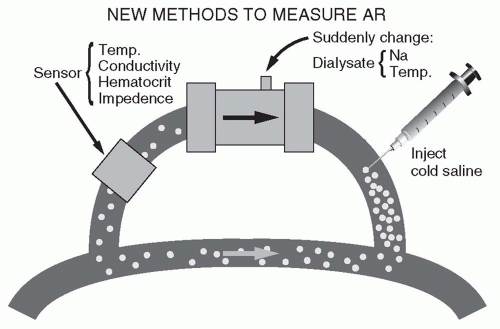 FIGURE 4.2 Principles of measuring access recirculation (AR). (Reproduced from Daugirdas JT. Hypertens Dial Clin Nephrol. 1997. Available at: http://www.hdcn.com.) |
8. Blood volume monitors. These use an ultrasonic or optical sensor operating on the inflow blood line to detect changes in hematocrit or plasma protein concentration during dialysis. Normally, in the course of fluid removal, increases in these blood values reflect the degree of plasma volume reduction. A claimed feature of such monitors is their ability to anticipate and prevent a hypotensive episode by reducing UF whenever a steep increase in hematocrit during dialysis has occurred or when a “crash crit,” identified during previous sessions, is being approached. Another potential use is to identify patients with covert fluid overload by recognizing that such patients tend to have only a minimal, or no, increase in hematocrit during dialysis despite fluid removal.
9. Single blood pathway (“single-needle”) devices. Most hemodialysis treatments are performed using two separate blood pathways: one to obtain blood from the patient and another to return blood to the patient. Several systems allow dialysis to be performed using a Y-shaped single blood pathway. Description and discussion of single-needle devices are beyond the scope of this book as they are used only rarely in the United States, however, their use is increasing in the context of home dialysis, notably, home nocturnal dialysis.
III. THE DIALYZER. The dialyzer is where the blood and dialysis solution circuits interact and where the movement of molecules between dialysis solution and blood across a semipermeable membrane occurs. Basically, the dialyzer shell is a box or tube with four ports. Two ports communicate with a blood compartment and two with a dialysis solution compartment. The membrane within the dialyzer separates the two compartments.
A. Structure. In the hollow-fiber (also called capillary) dialyzer, the blood flows into a chamber at one end of the cylindrical shell, called a header. From there, blood enters thousands of small capillaries tightly bound in a bundle (Fig. 4.3). The dialyzer is designed so that blood flows through the fibers and dialysis solution flows around the outside. Once through the capillaries, the blood collects in a header at the other end of the cylindrical shell and is then routed back to the patient through the venous tubing and venous access device. Historically, parallel plate dialyzers were also used, and in such devices, blood and dialysis solution pass through alternate spaces between the membrane sheets. In both configurations, blood and dialysate flows move in opposite directions, to maximize the concentration gradient between blood and dialysate in all parts of the dialyzer.
1. Membranes. Currently the majority of clinically used dialyzers utilize a membrane manufactured from synthetic polymer blends. Such membranes include polysulfone, polyethersulfone, polyacrylonitrile (PAN), polyamide, and polymethylmethacrylate (PMMA). It should be noted that whilst several manufacturers utilize polysulfone membranes, subtle differences exist between them, and consequently they cannot be considered as identical. Synthetic membranes are more biocompatible than the historically used membranes made from cellulose, and for this reason, as well as due to the fact that cellulose-based membranes were historically perceived to be low-flux membranes, the use of cellulose-based membranes has declined. In fact, unmodified cellulose membranes such as Cuprophan are no longer in production.
Cellulose membranes are made up of molecular chains that contain hydroxyl (OH) groups. These hydroxyl groups were largely responsible for the membranes’ poor biocompatibility. Numerous attempts have been made to
improve biocompatibility by chemically replacing the hydroxyl groups with acetate. Such membranes are known by their chemical name: cellulose acetate, cellulose diacetate, and cellulose triacetate depending on the number of the OH groups that were replaced in the cellulose molecule. Such membranes continue to be used clinically. Another approach has been the addition of a tertiary amino compound to liquefied cellulose during formation of the membrane. As a result, the surface of the membrane is altered, and biocompatibility is increased.
improve biocompatibility by chemically replacing the hydroxyl groups with acetate. Such membranes are known by their chemical name: cellulose acetate, cellulose diacetate, and cellulose triacetate depending on the number of the OH groups that were replaced in the cellulose molecule. Such membranes continue to be used clinically. Another approach has been the addition of a tertiary amino compound to liquefied cellulose during formation of the membrane. As a result, the surface of the membrane is altered, and biocompatibility is increased.
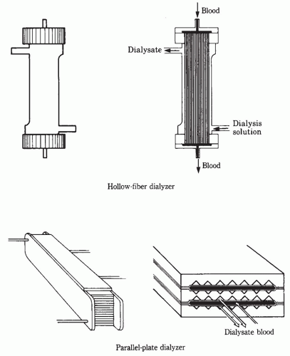 FIGURE 4.3 Blood and dialysis solution flow pathways through a hollow-fiber and parallel-plate dialyzer. (Modified from Man NK, Jungers P. Hemodialysis equipment. In: Hamburger J, Crosnier J, Grunfeld JP, eds. Nephrology. New York, NY: Wiley; 1979:1206, 1207.) |
2. Coated membranes. Improved biocompatibility has also resulted from the coating of the membrane with an antioxidant such as vitamin E. The clinical use of such membranes has resulted in an improved antioxidant profile in the blood
of patients using the device, and in some studies, reduced heparin requirements and reduced clotting.
of patients using the device, and in some studies, reduced heparin requirements and reduced clotting.
3. Protein-losing membranes. Because some uremic toxins are tightly bound to albumin, one school of thought has been to use membranes with a high albumin permeability deliberately. Albumin is lost during dialysis with the use of such membranes, but along with the albumin, protein-bound toxins would also be removed from the body. The clinical utilization of such membranes in routine dialysis treatment is not widespread. Very-high-molecular-weight cut-off membranes allow free passage of large macromolecules but still substantially restrict the passage of albumin. Such have been used in the treatment of patients with light chain deposition disease requiring dialysis for the removal of free light chains from the blood.
4. Membrane permeability to solutes and to water. The permeability to solutes and water of each class of dialyzer membranes can be altered markedly by adjusting the manufacturing process, changing the polymer ratio (which influences the membrane pore size distribution), or by adjusting the membrane thickness.
5. Membrane efficiency versus flux. The ability of a dialyzer to remove small-molecular-weight solutes, such as urea, is primarily a function of its membrane surface area multiplied by the permeability of the membrane to urea. A high-efficiency dialyzer is basically a big dialyzer that by virtue of its larger surface area has a high ability to remove urea. High-efficiency dialyzers can have small or large pores, and thus can have either high or low clearance for larger-molecular-weight solutes, such as β2-microglobulin (MW 11,800). High-flux membranes have large pores that are capable of allowing larger molecules, such as β2-microglobulin to pass through. Usually, β2-microglobulin clearances are not reported in standard dialyzer specification charts. High-flux membranes also have high water permeability, with coefficient of UF (KUF) values >10 mL/h per mm Hg, and usually >20 mL/h per mm Hg.
B. Interpreting a dialyzer specification sheet. Information usually provided about dialyzers includes KUF (UF coefficient) clearance of solutes such as urea, creatinine, vitamin B12, and phosphate (and occasionally β2-microglobulin); membrane surface area; priming volume; fiber length; and fiber wall thickness (Table 4.1).
1. KUF. The UF coefficient, as defined in Chapter 3, is the volume of plasma water filtered in milliliters per hour for each mm Hg of TMP. Dialyzer membranes can be classified into low-flux or high-flux varieties in accordance with their KUF and large-molecule clearance. There is no universal classification, but broadly speaking, dialyzers with KUF <8 mL/h per mm Hg can be regarded as low-flux, whereas those with KUF greater than 20 mL/h per mm Hg be regarded high-flux. Dialyzers having a KUF between 8 and 20 mL/h per mm Hg


Stay updated, free articles. Join our Telegram channel
Full access? Get Clinical Tree
