Fig. 1
Principles of 2PE microscopy. (a) Jablonski energy diagram showing the electron excitation process in single- (left ) and two-photon (right ) fluorescence microscopy. Single-photon excitation (left ) requires the absorption of a high energy photon to excite an orbital electron of a fluorophore to a vibrationally and electronically excited state (excitation). When this electron relaxes to its ground state, it emits a photon of light of a different wavelength than the excitation photon (fluorescence emission). In 2-photon excitation (2PE; right ), this process is achieved by the quasi-simultaneous absorption of two photons; the first one excites the electron to a virtual intermediate state, and the second one completes the excitation to reach the electronic excited state. (b) Confocal versus 2PE microscope systems. In confocal systems (left ), the presence of a pinhole right before the photodetector rejects the photons emitted from outside the focus (e.g., photon #6), as well as those scattered on their way to the PMT (e.g., photon #4). Only unscattered photons coming from the focal plane are able to pass through the pinhole (e.g., photon #5) and contribute to the signal. In 2PE systems (right ) there is no need for a pinhole since photons contributing to the signal come only from the geometrical focus of the excitation spot (e.g., photon #5), even if they were scattered on their path to the PMT (e.g., photon #4)
The main shortcoming of single-photon excitation is its inefficient fluorescence excitation: because light absorption occurs throughout much of the specimen, a pinhole in front of the detector is required in confocal microscopy to reject fluorescent photons emanating from outside the focus (Fig. 1b). Unfortunately, the pinhole similarly rejects in-focus photons that subsequently scatter, and as a result only unscattered photons contribute to the signal. This inefficiency demands high laser power for imaging, which creates unwanted photodamage [9] and limits imaging depth to the free mean path of visible light (≤100 μm in biological tissue [10]).
In 2PE, two lower energy photons are absorbed simultaneously to excite the fluorophore. Because of the steep dependence of absorption rate on photon concentration (light intensity), fluorescence is confined to the geometrical focus of the laser excitation spot, which provides inherent optical sectioning. A pinhole is not required because all emitted photons (regardless of how much they scatter on their path to the detector) convey a useful signal (Fig. 1b). Greater tissue penetration is possible in 2PE (compared to confocal microscopy) thanks to the longer excitation wavelength used and to the ability to collect scattered emission photons as a useful signal. These properties of 2PE also limit photodamage since the absorption is confined to a tiny focal volume, and fewer excitation events are required to achieve the same signal due to the improved collection efficiency. In addition, because 2PE microscopy requires photons of lower energy than those used in one-photon excitation, this reduces photodamage further.
2 Materials
2.1 Instrumentation: Laser and Microscope
Although commercial systems are available for multiphoton microscopy, some users may prefer to custom build their 2PE microscope (Fig. 2). Because the hardware and software needed for laser beam scanning and data acquisition in 2PE and confocal microscopy are so similar, commercial confocal systems can sometimes be converted into a two-photon microscope [11]. For further reading on configuring a 2PE system, please refer to the following resources [3, 8, 9, 12].
Fig. 2
Components of a 2PE microscope. The basic components of a 2PE microscope include the following elements: the two-photon laser (Ti:sapphire laser), a beam expander (the goal is to fill the back aperture of the objective lens), a half-wave plate combined with a polarizing cube to control and measure the laser power, a fast shutter to control exposure, scanning mirrors (vertical and horizontal, in this example they are closed-loop galvanometer mirrors), a scan lens, a tube lens, a dichromatic mirror, the objective, a collection lens, the photomultiplier tubes, and a CPU to integrate and control the image acquisition process
Mode-locked lasers are well matched to the requirements for efficient 2PE (short pulse width of 50–100 fs and high repetition rates of ~100 MHz). In particular, tunable femtosecond Ti:Al2O3 (titanium:sapphire) lasers are commonly used in most laboratories because the spectral range (690–1,050 nm) is sufficient to excite a wide variety of available fluorophores. Fixed wavelength mode-locked lasers in the 1,000–1,250 nm range (e.g., Nd:YLF, Yb:KYW, or Cr:forsterite) can also be used, for example, to image red-shifted fluorescent proteins [13], and they are more affordable than tunable lasers. Longer wavelengths of ~1,300 nm can be achieved when an optical parametric oscillator (OPO) is coupled to a standard Ti:Al2O3 laser; this configuration may be desirable to achieve deeper tissue penetration [14] or multicolor imaging [12]. Others have reached record depths of imaging using regenerative amplifiers as the excitation source, which lower the laser repetition rate and thereby increase the yield of nonlinear optical processes [10, 15].
In addition to the laser, the main components in a standard 2PE microscope are a beam expander, a fast shutter, scanning mirrors (closed loop or resonant), photomultiplier tubes (PMT), and the different optical components (e.g., scan and tube lenses, reflecting and dichroic mirrors, objective lens), needed to guide the laser beam to the sample and the emitted light to the PMTs (Fig. 2).
2.2 Image Acquisition and Image Processing Tools
For custom microscopes several image acquisition and image processing tools have been developed:
1.
ScanImage [16] is an image acquisition application for controlling laser scanning microscopes. It was developed in MATLAB (The MathWorks, Inc.) and is currently used by >150 laboratories worldwide (https://openwiki.janelia.org/wiki/display/ephus/ScanImage). This versatile software uses simple graphical user interfaces to operate the scan mirrors (scan speed, zoom, rotation) and define the properties of the images to be acquired (e.g., number of slices in a stack, step size), as well as settings to carry out uncaging experiments.
2.
Another helpful application is ImageJ (http://rsbweb.nih.gov/ij/) and some of its plug-in collections (www.macbiophotonics.ca/imagej; http://www.uhnresearch.ca/facilities/wcif/imagej/), which are used for image processing and analysis.
3.
Neurolucida (MicroBrightField, Inc.) and its confocal image stack module is a commercial software that can be used to trace and analyze complete axonal and dendritic arbors of neurons within image stacks acquired with 2PE and extract useful information (e.g., length, branching nodes, branch order, complexity index, etc.) to characterize the neuron imaged. Standard tools for analysis of calcium imaging data (see Subheading 3.4) are still being developed [17], and individual labs use custom routines usually written in MATLAB.
3 Methods
3.1 Making the Brain Visible for 2PE Microscopy: Fluorescent Labeling of Cells and Tissues
Both synthetic dyes and fluorescent proteins are available to image the structure of neurons and glia in the brain (e.g., tracing the dendrites and axons of particular neuronal types) or to record neuronal activity with calcium imaging. Commonly used synthetic dyes for imaging neuronal structure with 2PE include Lucifer yellow, Alexa fluor, DiI, and fluorescein. Intravascular injection of fluorescent dextrans permits the study of blood flow dynamics at the level of capillaries in the superficial layers of the cortex [18–21]. In addition, methoxy X-O4 is a fluorescent compound that crosses the blood-brain barrier and binds to amyloid plaques in mouse models of Alzheimer disease [22]. Synthetic calcium indicator dyes include Fluo-4, Fura-2, and OGB-1. Suforhodamine 101, a red dye that labels glia [23], is commonly used in calcium imaging experiments to distinguish neurons from glia.
A wide array of fluorescent proteins also exists over a rainbow palette of colors that allow an increasing number of applications [24, 25]. For example, EGFP, YFP, mCherry, and td-Tomato are frequently used for imaging neuronal structure with 2PE, while TNXXL, YC3.60, and GCaMP6 have been developed as genetically encoded fluorescent calcium indicator proteins [26–29] (see Note 1 ). For in vivo imaging of brain cells, specific cell subsets can be labeled with fluorescent proteins through an array of genetic methods (alone or combined). Below we discuss briefly the most commonly used methods for labeling cells for imaging with 2PE:
1.
Filling cells with synthetic dyes: For live imaging of neural structure with 2PE microscopy, cells can be labeled with fluorescent dyes using Diolistics [30], by direct injection of dyes into the brain or by filling them with a particular dye during whole-cell recordings [31]. Similarly, synthetic calcium dyes can be introduced directly into cells or electroporated using a patch pipette [32]. Alternatively, the acetoxy-methyl ester (AM) variants of dyes like Fluo-4 or OGB-1 can be bulk-loaded into the brain, which allows for recording the activity of large ensembles of neurons [33–35].
2.
Transgenic and gene targeting (see Note 2 ): Mice engineered to express fluorescent proteins under the control of specific promoters (e.g., thy1 promoter; [36]) have been used for chronic imaging neuronal structure in vivo for a decade [37, 38]. The use of conditional gene expression (e.g., Cre-loxP, Flp-FRT) and inducible systems (e.g., Tet-ON/Tet-OFF) provides further spatial and temporal control of gene expression [39].
3.
Transfection methods: In the context of live cell imaging with 2PE, nucleic acids (DNA or shRNA constructs) are most commonly introduced in neurons using plasmid electroporation or viral infection. These methods can be used in Cre mice for conditional gene activation to obtain higher labeling specificity [39]. For in vivo electroporation, the delivery of a plasmid into neurons of living mice is achieved by injecting a DNA solution into the brain (or into a single cell with patch-clamp electrophysiology) followed by short electric pulses that permeabilize cell membranes temporarily and allow plasmid entry [40]. For in utero electroporation, the DNA is injected into the cerebral ventricles in mouse embryos in order to target subpopulations of neuron precursors (e.g., layer 2/3 pyramidal neurons of the cerebral cortex) [41–43]. Recombinant viruses (e.g., adenoviruses, lentiviruses, herpes viruses) are increasingly used for gene delivery into neurons, typically via stereotaxic intracranial injections targeted to a particular brain region [44–46].
3.2 Cranial Window for In Vivo 2PE Microscopy
Two different surgical preparations, glass-covered cranial window and thinned skull, have been developed to get optical access to the brain and image structure and functionality of labeled neurons [47–50]. The cranial window preparation requires the removal of a piece of skull (leaving the dura intact), and then the craniotomy is covered with a tiny glass coverslip (Fig. 3). The thinned skull preparation requires mechanical thinning of the superficial layers of the skull, preserving a thin layer of the bone that allows imaging through it. There is also a variant of the thinned skull approach, in which the skull is thinned, polished, and ultimately reinforced with a layer of cyanocrylate glue and a cover glass [51]. With any of these methods, one can achieve sufficient spatial resolution with 2PE microscopy to detect individual dendritic spines or axonal boutons.
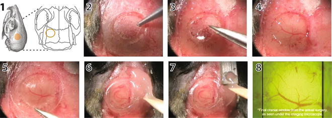
Fig. 3
Cranial window surgery for in vivo imaging with 2PE microscopy. The location of the cranial window is selected based on anatomical landmarks or functional imaging (1). In this case, the window was placed over the left barrel cortex. Under anesthesia, the skull is exposed, and a circular portion of the bone is gently carved with a pneumatic drill (2). Next, the bone flap is removed with small forceps (3) taking care not to damage the underlying meninges and vasculature (4). A glass coverslip is gently placed over the craniotomy (5). The edges of the glass window are sealed with cyanoacrylate glue and dental cement (6). A small well is also made around the window with dental acrylic to accommodate the objective lens and a drop of water for imaging. A titanium bar is then embedded in the dental acrylic (7), which can later be used to attach the mouse on to the microscope stage. The cortical vasculature can be seen under the microscope objective (7). Please refer to Mostany R and C Portera-Cailliau (2008) for a video of the procedure
The main advantage of the glass-covered cranial window method is that it allows for multiple imaging sessions to be conducted for longitudinal imaging of the same neuronal or glial processes within large fields of view. The cranial window approach (but not the thin skull preparation) also makes it possible to perform certain manipulations of the brain before sealing the craniotomy with a cover glass (e.g., electrode implantation, direct intracortical pharmacology, bolus loading of calcium dyes, viral injections). In addition, craniotomies are necessary for implanting gradient refractive index lenses (GRIN) in experiments that require imaging of deep brain structures [52] (see Note 3 ). The main drawback of the cranial window method is that it is more technically demanding as only the best preparations remain optically transparent for weeks or months, and even the slightest perturbation of the dura mater will cause a quick worsening of the quality of the imaging. Because the skull is never breached with the thinned skull technique, the incidence of infection and inflammation is minimal, and the success rate is much higher [53]. One downside of transcranial imaging is that skull thinning, which has to be repeated before every imaging session, can only been done a limited number of times (<3), or else the quality of imaging deteriorates. In this regard, the polished and reinforced preparation avoids the bone inflammation that results from repeated thinning [51].
3.3 Imaging Neuronal Structure with 2PE Microscopy
The structure and function of different cell types in the brain that express fluorescent dyes or proteins can be imaged in vivo using 2PE microscopy allowing the study of dynamic anatomical and functional changes as a result of learning and memory or in response to sensory inputs from the environment, or how they compensate for or degenerate in disease. The extraordinary resolution of the images acquired with 2PE microscopy makes it possible to observe tiny neuronal structures, such as spines and axonal boutons (~1 μm in diameter), and even quantify the turnover and trafficking of synaptic proteins (e.g., PSD95, Ras) within these structures [13, 54]. In the last decade, several studies that imaged synaptic structure in vivo with 2PE were able to record changes in synapses that were either associated with sensory experience and learning motor tasks (reviewed in [55, 56]), or triggered by stroke [18]. Chronic 2PE microscopy in vivo can also be used to image neuroglial [57] and neurovascular [51] interactions, blood flow dynamics [21, 19], and amyloid plaques [58, 59], among others. By imaging neurons in the intact brain of living mice, such longitudinal, high-resolution imaging studies of dendritic and axonal segments have provided valuable information about dynamic aspects of synapses that could not previously be examined using histological studies in fixed tissue (Fig. 4).
Fig. 4
Chronic high-resolution imaging of dendritic spines with in vivo 2PE microscopy. High-resolution images of dendritic spines acquired with in vivo 2PE microscopy before and after stroke. The day of imaging is shown in the lower right-hand corner. Shown is an apical dendritic segment from a layer 5 pyramidal neuron in peri-infarct cortex before (green ) and after (red ) unilateral permanent middle cerebral artery occlusion (MCAO) in mice. All images are maximum intensity projections (4–7 slices, 1.5 μm apart). A few examples of always present spines (yellow arrowheads ), gained spines (green arrowheads ), and lost spines (red arrowheads ) are shown. Blue asterisks at +4 d post MCAO denote transient dendritic swelling after stroke. See Mostany et al. [18] for details
3.4 Recording Neuronal Signals with 2PE Microscopy
3.4.1 Calcium Imaging
When neurons fire action potentials, the intracellular concentration of calcium ions rises. One can record neuronal activity optically by using fluorescent dyes (or proteins) that respond to binding of calcium by changing their spectral properties (e.g., their fluorescent intensity increases or decreases, or their excitation/emission spectra change). Calcium imaging using 2PE microscopy is an ideal tool for interrogating large ensembles of neurons in the intact brain [32] because it offers advantages over traditional single unit recordings using microelectrodes. First, with calcium imaging one can record signals from hundreds (potentially thousands) of neurons simultaneously. When combined with mouse genetics to label individual subpopulations of neurons, one can also be certain of which cell types the calcium signals are being recorded from. Second, calcium imaging is less invasive, and circuits can be recorded without penetrating electrodes that might disrupt normal activity.
For calcium imaging, one can use 2PE microscopy to record calcium transients in single dendritic spines [60, 61] or to monitor the spontaneous or evoked activity of large ensembles of neurons simultaneously with single cell resolution [62–64] (Fig. 5).
Fig. 5
Calcium imaging of neuronal ensemble activity with 2PE microscopy. (a) Typical field of view of layer 2/3 neurons (green) and glia (yellow) stained with the calcium indicator dye Oregon Green BAPTA-1AM and imaged with in vivo 2PE microscopy. Sulforhodamine 101 (a red dye) was used to stain glia. The image is a single frame (~120 μm below the dura) in a representative calcium imaging movie (3 min, 3.9 frames per second) from a 14-day-old mouse. (b) Calcium traces showing the relative changes in fluorescence intensity over the baseline fluorescence (ΔF/F) of 5 different layer 2/3 neurons from a representative calcium movie. The upward deflections represent spiking events within those neurons
Unfortunately, two-photon calcium imaging suffers from important drawbacks, such as poor temporal resolution and low signal-to-noise ratio [17, 65]. Newer generation genetically encoded calcium indicators with improved signal-to-noise will overcome some of these limitations. For example, although synthetic indicators are superior for detecting single spikes, some of the newer genetically encoded indicators (YC3.60, GCaMP6f) may detect action potentials quite reliably [66]. Importantly, recent developments in faster scanning (e.g., acousto-optical deflectors), parallelization of 2PE (e.g., multifocal multiphoton microscopy), and improved photodetectors suggest that over the next decade optical probing of neural activity with calcium imaging could eventually be an excellent alternative to electrophysiology, offering a less invasive approach to record action potential firing in large ensembles of identifiable neurons in three dimensions (see Subheading 4, step 2).
3.4.2 Voltage-Sensing Proteins
Another way to optically probe neuronal activity is to image changes in membrane potential. For this purpose several voltage-sensing proteins (e.g., FLaSh, VSFP2, SPARC, Flare, Opto-patch) have been designed that work well with 2PE microscopy and could in theory be useful to monitor the activity of thousands of individual neurons simultaneously [67–69]. These sensors are usually FRET based and can report both subthreshold changes in membrane potential and spiking activity of neurons. Unfortunately, most current approaches for voltage sensing with genetically encoded or synthetic indicators have poor spatial resolution and very low signal-to-noise ratio, requiring the averaging of many stimuli to detect responses.
3.5 Combining 2PE Microscopy with Optogenetics, Glutamate Uncaging
Another advantage of 2PE microscopy is that it can easily be combined with optogenetics and be used to uncage neurotransmitters for temporally and spatially precise manipulation and probing of neuronal activity within intact neural circuits.
3.5.1 Optogenetics
This technique enables researchers to silence or stimulate genetically specified classes of neurons (or other electrically excitable cells) with exquisite temporal precision using light-sensitive molecules [70, 71]. For example, channelrhodopsin-2 (ChR2) is a light-activated cation channel that depolarizes neurons, whereas halorhodopsin (NphR) and archaerhodopsin-3 (Arch) are a chloride channel and an outward proton pump, respectively, that enable almost complete silencing of neurons. Using optogenetic tools, cell type-specific and minimally invasive photostimulation has revealed causal relationships between activity of neuronal populations and animal behavior. In addition to evoked behaviors, electrophysiological recordings (e.g., patch-clamp or “optrodes”) [72] or calcium imaging [73] can be used as the readout of neuronal activity. Thus, by combining 2PE microscopy with calcium dyes or voltage-sensitive dyes, subsets of neurons expressing optogenetic sensors could be specifically modulated with light to reveal and mimic patterns of connectivity with phenomenal temporal and spatial precision [74]. In the future, as improved red-shifted calcium indicator dyes become available, it will be easier to combine optogenetics with two-photon calcium imaging. Although optogenetic manipulations are by enlarge done with single-photon excitation, 2PE of ChR2 is possible in vivo [75], and this option may be preferable when precise stimulation of individual synapses or portions of circuits is desired.
3.5.2 Two-Photon Uncaging
The photorelease of caged, biochemically inert effector molecules (e.g., nucleotide, neurotransmitter, second messenger) can be used to control molecular interactions in cells [76]. With two-photon uncaging, the absorption energy is used to release the caged molecule, typically a neurotransmitter, from its protective chemical group, in order to mimic normal synaptic activity. The photoactivation of caged neurotransmitters has achieved synapse-specific resolution with the use of 2PE in brain tissue. By combining 2PE and uncaging (e.g., of MNI-glutamate), postsynaptic receptors of individual spines can be stimulated with excellent temporal and spatial resolution while structural and activity changes are assessed. These techniques have been successfully applied to the study of postsynaptic signaling and local circuit mapping at the level of individual dendritic spines [77–79]. An exciting recent advance was the successful stimulation of identified dendritic spines in vivo, in adult mice, using two-photon uncaging [80].
3.6 Future Directions
The invention of 2PE microscopy has revolutionized fluorescence imaging over the last 2 decades, thanks to the vision of physicists, chemists, engineers, and biologists working towards a common goal. Over the next few years, we will continue to witness unprecedented advances that lead to additional improvements in this powerful tool. In particular, developments that will enhance our ability to image deeper in the brain and with better temporal resolution in awake behaving mice will be especially useful.
3.6.1 Deeper and Brighter Imaging
Light scattering of both the near-infrared excitation wavelengths used in 2PE microscopy and of the emitted fluorescence imposes limits on how deep one can image [81]. As a result, in vivo calcium imaging with conventional 2PE has been restricted to the superficial layers of the neocortex. A variety of approaches have been established to increase the depth range for in vivo calcium imaging, including the use of high numerical aperture objectives and longer wavelengths (e.g., with fixed-wavelength laser sources or OPOs), using adaptive optics and wavefront optimization to correct for spherical aberrations and lensing effects [82, 83] or implementing ultrashort-pulsed regenerative amplifiers [15]. An alternative approach to deeper imaging is to improve on the collection of scattered fluorescent emissions that are not transmitted through the objective and would otherwise be a wasted signal, for example, by using a ring of optical fibers around the objective [84]. A different approach entirely is to use microendoscopes to reach deep brain structures, such as the hippocampus [52, 85]. In addition, signal-to-noise ratios will improve as better fluorophores become available. For calcium imaging this is a critical issue, because when faster scanning is implemented (see below), the pixel dwell time of the laser will be reduced, resulting in less signal from the indicator. Major efforts are underway to design better genetically encoded calcium indicators to solve these problems [28].
Stay updated, free articles. Join our Telegram channel

Full access? Get Clinical Tree


