Fig. 1
(a) Illustration of the cornea, the IOP and applanation length; (b) the Corvis device from two different angles; (c) the cornea image it takes
2.2 Geometry Modelling
The Corvis system was simplified as a working domain consisting of a nozzle, a cornea, and an air space. Their respective geometric modelling is described below.
2.2.1 Air Space
The air field was designed as an open space consisting of a circular enclosure (500 mm in diameter, 16 mm in height) where the nozzle and the cornea were placed at the centre (Fig. 2). The space was designed to be much larger than the cornea to avoid the influence of rebounding air flow from the wall.
2.2.2 Cornea
Taking the measurements made by the Corvis ST device into account, the cornea was modelled as a dome-shaped elastic solid. We used a constant thickness of 0.52 mm, a horizontal diameter of 10 mm, and a vertical height of 2.6 mm to approximate the cornea in this initial work (Fig. 2).
Fig. 2
The entities in the working domain: the open space, the nozzle, and the cornea
2.2.3 Air Nozzle
The nozzle was configured as a hollow pipe 3.08 mm in diameter placed 11 mm from the cornea, as per the Corvis manual [5].
Using the grid generator within ANSYS, an adaptive mesh was generated for the air space where the smallest element size was 1 mm. A fine mesh was created at a region under the nozzle and the discharging area. The final fluid mesh contained 4,784,871 tetrahedron elements and 844,235 nodes, the cornea mesh contained 44,409 elements and 70,148 nodes (Fig. 3).
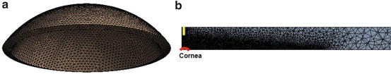
Fig. 3
Computational grid for: (a) the cornea; (b) the enclosure space (adaptive mesh)
2.3 Biomechanics Modelling
2.3.1 Fluid Solver
With the aim of modelling air flow through a pipe and the resulting effect on the cornea. The ANSYS CFX software was used for air flow simulation. A κ–ω turbulence model was used for flow modelling. The flow was treated as transient and the highest flow velocity from the outlet of the nozzle was set as 80 m/s. Therefore the airflow had a brief and strong pressure impact on the cornea. The wall was treated as outlet of the domain.
The air flow was treated as transient so that the airflow had a brief and strong pressure impact on the cornea. The jet inflow from the nozzle was approximated by a sinusoidal wave (Fig. 4). A κ–ω model was used for air turbulence modelling.
2.3.2 Solid Solver
With different fibre orientations in the corneal centre and periphery, the mechanical properties of the cornea are very complex. In this work we employed a much simpler Neo-Hookean strain energy function:
where μ is the initial shear modulus, d is the incompressibility parameter,  is the invariant of the Cauchy–Green deformation tensor, J is the determinant of the elastic deformation gradient. The shear modulus ( = 100 kPa) was computed using the relationship:

where a Young’s modulus E = 225, 000 Pa and a Poisson’s ratio ν = 0. 49 were assumed in all calculations (refer to [2] E = 0. 3 MPa, ν = 0. 49). The ANSYS interface requires the initial shear modulus and the incompressibility parameter to be specified. The remainder are automatically computed and exploited by the software to fit the model to the experimental data.
(1)
is the invariant of the Cauchy–Green deformation tensor, J is the determinant of the elastic deformation gradient. The shear modulus ( = 100 kPa) was computed using the relationship:(2)
Stay updated, free articles. Join our Telegram channel

Full access? Get Clinical Tree


