Fig. 1
Brain–skull interface (a) lateral section through human head showing the brain and surrounding tissue (taken from NAMIC registration case inventory brain) (b) detailed representation of the meninges (modified from Haines et al. [12])
In this study we have conducted ex vivo uniaxial compression tests on a sample containing skull, meninges and brain and the simulations of the experiment to establish mechanical behaviour and properties of brain–skull interface. All the necessary ethical approvals were obtained prior to the experiment from Animal Ethics Committee, University of Western Australia (UWA). The approach ensured we could examine brain–skull interface in its closest natural state in a controlled study.
2 Materials and Methods
2.1 Sample Preparation
Sheep heads were collected from Royal Perth Hospital (RPH), Perth. The specimens were taken as by-product of anaesthesia training programme. They were sacrificed using high dose of triple drip (a combination of xylazine, ketamine and guaifenesin, all anaesthetics compound). They were transported to the testing facility in a sealed container and stored at 4° C before further processing and testing. Samples were tested within 24 h from the time of death to reduce variability due to post-mortem changes [13]. The specimens were not frozen at any time.
The heads were skinned and a rectangular cut of ∼30 × 30 mm was made on the skull on top of the cranium (above cerebrum) using vibrating saw. Adjoining cut of ∼30 × 10 mm was also made. Using a microtome blade (Feather s35) the underlying brain was cut vertically in sagittal and coronal plane through the opening in skull. The smaller of the skull was removed along with the underlying brain tissue using forceps and scalpel to create an opening into cranium and the sample. From the opening, a horizontal cut (in transverse plane) was made in the brain leaving approximately 12 mm of tissue attached to skull using a bent razor blade. The free specimen was lifted out from the skull with the blade to ensure minimal damage to the meninges. The skull was set on epoxy putty (Selleys Knead It Multipurpose) base to roughly level the four corners of skull. The putty set in 10 min. The top surface of the brain was carefully levelled using microtome blade. ∼5 mm of brain tissue from all edges was removed using microtome blade and scalpel to ensure we discarded damaged meninges and tissues in the edges that may have been caused by the vibrating saw. This formed our test sample (with brain–skull interface). The process can be seen in Fig. 2a–g.
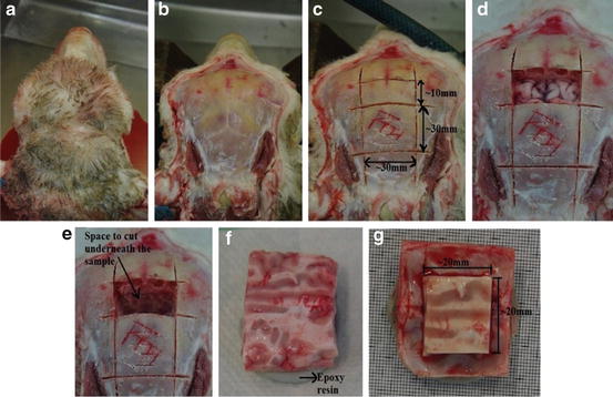
Fig. 2
Sample preparation (a) head (b) skinned for extraction (c) skull cut using vibrating saw, lower ∼30 × 30 mm and upper ∼10 × 30 (d, e) smaller free skull and brain removed (f) sample extracted and mounted in epoxy resin (g) complete sample A
The resulting sample had brain tissue resting on skull with brain–skull interface intact. The width of the faces of brain tissue, position of four corners in contact with the skull and height at the corner of sample were measured. The widths of the faces of the samples were taken midway between the base and the top surface of brain tissue.
2.2 Experimental Set-Up
Uniaxial compressions of the samples were performed in set-up shown in Fig. 3. The experiment was done in a testing device developed in-house [14]. The displacement of impermeable loading plate was done by Haydon Kerk Linear actuator 43F4A-3.22-099, a stepper motor screw drive actuator. It has a displacement control of 7.9 μm per step and allowed loading velocities of 0.001–5 mm/s. The displacement was measured by MTS CS core sensor with analog output. The forces were measured by Burster 8523-20 0-20N loadcell with linear output in the required range of 1 N with error less than 0.15 % [14]. The experiment was documented using Pentax K5 camera with FA 50 mm f1:1.4 lens. The images were used to study deformation of samples after the experiment.
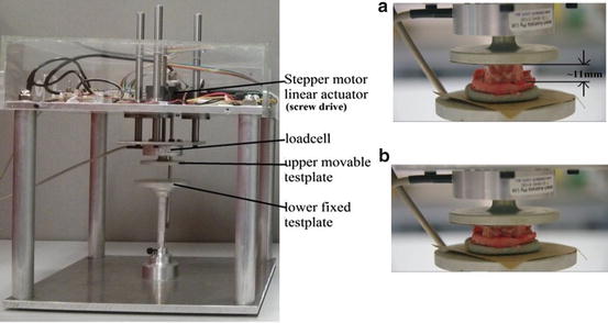
Fig. 3
Experimental set-up (a) sample before compression (b) sample after compression
2.3 Experimental Protocol
The experimental protocol follows Miller and Chinzei [15]. The samples were compressed between two impermeable platens in a semi-confined uniaxial set-up. No preconditioning was done to the samples.
Tests were done at two different loading speeds 1 and 0.01 mm/s. The tests were performed at room temperature as suggested by literature [13, 15, 16]. The movement of the platen began about 0.5 mm above the sample and care was taken that the sample didn’t touch the loading platen before compression started. The samples were compressed about 3 mm corresponding to approximate strain of 0.3. 120 grid sand papers were glued to both the platens to ensure no relative movement occurs between sample and loading plates, so no slip boundary condition could be used in the analysis.
The linear stepper motor, screw drive actuator had very high acceleration and hence the loading velocity was assumed to be achieved instantaneously.
2.4 Analysis
Dimensions of brain tissue in both the samples were measured. Geometry of internal surface of skull was required to create a model for both samples. After the experiment, the brain tissue and meninges were scraped from the skull and the internal surface of the skull was scanned using MODELA MDX-20 Scanner. The scanned surface of skull and the initial dimensions of the brain tissue were used to create models of the samples. Side walls of brain were assumed to be orthogonal and the top surface was assumed to be parallel to sample resting plane. Skull was assumed to be rigid body as it was orders of magnitude stiffer than brain tissue. Computational grid was created on the geometry. All the pre-processing of the model including mesh generation was done using Altair HyperMesh. The brain tissue was modelled using the Ogden-type [17]. Hyperelastic model as proposed by Miller and Chinzei [16].
where W is strain energy potential, λ i principal stretches, μ relaxed shear modulus and α material coefficient. The experiment was simulated by applying fixed boundary condition at the skull and prescribed displacement at top surface of brain as shown in Fig. 4. The interface was simulated as friction less sliding contact. Loading surface reaction force-time relation was obtained from simulation using ABAQUS™ was matched close to data measured by the experiment to determine coefficients μ and α following Morriss et al. [18]. This formed subject specific material property of brain tissue for the sheep from which the sample was taken.
(1)