Fig. 1
Moiré fringes. (a) and (b) are two examples of fine patterns. When one is superimposed onto the other, a coarser beat pattern—moiré fringes—appears (c)
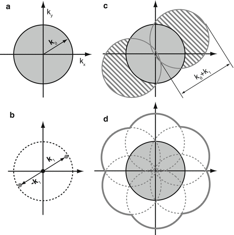
In optics, reciprocal space (also known as spatial-frequency space or Fourier space) is often a more informative representation of the physical reality, especially when spatial resolution is concerned [4]. In reciprocal space, low- and high-resolution information occupies locations close to and far away from the origin, respectively. The lateral resolution limit of a microscope can be conveniently represented by a circle whose radius is proportional to the numerical aperture and the inverse of the wavelength (Fig. 2a). All high-resolution sample information outside of the circle is lost through imaging; only the region inside the circle is observable to the microscope. A sinusoidal laterally structured excitation pattern corresponds to three frequency points (Fig. 2b). The product of this pattern and the dye distribution amounts to the translation of sample information in reciprocal space along the arrows drawn from the origin to those points (Fig. 2c); in particular, information normally outside of the circle can be shifted into the circle and become effectively observable as moiré fringes (Fig. 2c). However, the extra information is mixed together additively with the normal resolution information and therefore needs to be separated. The only way to do so is by acquiring enough images (three in this case) to be able to solve a set of linear equations. Each image is taken with a different phase of the same excitation pattern. As a result, lateral resolution enhancement happens only along the line perpendicular to the excitation pattern stripes (Fig. 2c). To obtain nearly isotropic resolution, the pattern needs to be rotated to two other angles equally spaced by 60°, and additional data needs to be acquired for all pattern orientations. With all the components available from all pattern orientations, represented by the seven circles in Fig. 2d, they are then “stitched” back together according to their original positions in frequency space, forming a final reconstructed image with extended resolution (Fig. 2d).


Fig. 2
Principle of structured illumination—lateral resolution enhancement. (a) A microscope’s observable region of frequencies in reciprocal space; the resolution limit is represented by the radius of the shaded circle, |k 0|. (b) The frequencies of a simple sinusoidal intensity pattern, represented by the three dots in reciprocal space. When the pattern is formed by an objective lens, the highest frequencies cannot exceed the dashed circle because the pattern formation is also resolution limited. (c) Illuminated under the pattern shown in (b), the frequencies in the hatched areas are translated into the normal observable region and hence become effectively observable. Resolution limit is now represented by |k 0| + |k 1|. (d) Excitation patterns of the same period but of different orientations are applied to extend the lateral resolution isotropically
1.2 Axial Resolution Enhancement
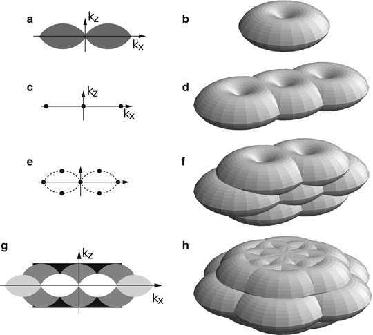
The axial resolution in 3D wide-field microscopy is much lower than the lateral resolution, especially for low-resolution features. This is reflected in reciprocal space by the shape of the observable region in 3D (Fig. 3a, b): its variable axial depth is about 1/3 of its lateral diameter at most and approaches 0 near the origin. Although the same idea of lateral resolution enhancement by structured illumination can be applied for the axial case, the same excitation pattern would not work (Fig. 3c, d) since it is structured only in the lateral direction; instead, what is needed is an axially structured illumination pattern. One such illumination pattern, as seen in reciprocal space, has frequency components above and below the k x –k y plane (Fig. 3e), translating sample information axially and making information above and below the normal observable region effectively observable (Fig. 3f–h). Compared to lateral-only structured illumination, two more lateral information components are present in the raw data, and therefore, five in total need to be separated. This means that five raw images within each pattern orientation and at each 3D defocus, acquired at five different lateral pattern phases, are needed in order to solve the five unknowns.


Fig. 3
Principle of 3D SIM. Observable regions for the conventional microscope (a and b), for structured illumination microscopy using two illumination beams (d), and three illumination beams in one (f) or three (g, h) sequential orientations. (a) and (g) are the k x–k z cross section of the 3D observable regions shown in (b) and (h), respectively. The spatial-frequency components of the structured illumination intensity for the two-beam (c) and three-beam (e) case. The dotted outline in panel (e) indicates the set of the highest spatial frequencies that are possible to generate by illumination through the objective lens; compare with the observable region in panel (a)
2 Materials
2.1 SIM Hardware
2.1.1 3D or TIRF Wide-Field Microscope, Either Commercial Body or Home-Built
A SIM microscope can be constructed around a commercial inverted microscope body; alternatively, it can be built on a damped optical table without requiring a microscope body. All SIM implementations to date take the form of a wide-field fluorescence microscope with inserted optical components in the excitation path for generating the illumination pattern (with the exception that some setups use more than one objective, as briefly discussed in Notes 2 and 3 ). One consideration is that of thermal drift. This is especially a problem for setups that cannot quickly switch between different phases and orientations of the pattern, as is the case in the grating-based SIM discussed below. While modest drift between different orientations of the pattern can be corrected for in the post-processing algorithm, drift within a phase series is more challenging to correct. As might be expected, thermal drift is negligible for setups that are designed to capture the movement of living cells and therefore must quickly switch between illumination patterns.
2.1.2 Diffraction Grating or Spatial Light Modulator
In Subheading 3, we will discuss two diffraction-based methods to generate the sinusoidally varying excitation pattern for SIM. One method uses a transmission phase grating that is mechanically manipulated to produce all the phases and orientations of the pattern. While simple, this method is inherently slower than an alternative we discuss, which relies on a spatial light modulator (SLM) to electronically generate the pattern. Non-diffraction-based ways of generating an illumination pattern are also possible as discussed in Note 4 .
2.1.3 Lasers
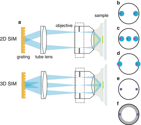
An important factor to consider when designing a structured illumination microscope is the coherency properties of the illumination source (Fig. 4a). Fully incoherent sources, like lamp illumination, can be used but will do little for resolution improvement. On the other hand, laser light can be tightly focused at the edge of the back pupil, generating the finest illumination pattern and thus the highest resolution improvement. However, the ultra-long coherence lengths of lasers can create stray interference patterns that are problematic for the reconstruction software. To alleviate this problem, it is possible to spatially scramble laser light (see Note 5 ), creating a partially incoherent source. In this case, every point in a source beam is incoherent with every other point in that same source beam, but is coherent with its corresponding point in the other source beams (Fig. 4b, c). This is especially attractive in 3D SIM imaging because it helps to confine the excitation light in the axial direction. However, this partial incoherence can lead to degradation in the zeros of the pattern especially at high angles of incidence that are used in TIRF or near TIRF (Fig. 4d). For this reason and also because of the stringent requirement on the placement of illumination beam at the rear pupil (Fig. 4e, f), in all the SIM–TIRF setups described [5, 9], a fully coherent source was used. In this case, the microscope should be searched for causes of any stray interference patterns (see Note 6 ).


Fig. 4
(a) A simplified schematic of a 2D or 3D structured illumination excitation path. Beams diffracted from a grating (diffraction orders) are focused to the edges of the objective back focal plane (pupil). In 3D SIM, three beams are used to create a pattern with both lateral and axial components. (b) Spatially scrambled laser light generates a “partially incoherent source”; that is, the points within one diffraction beam are all incoherent with each other (blue), but corresponding points (pink) in the other diffraction orders are coherent with each other. (c) In 3D structured illumination microscopy, this had the advantage that the axial excitation light is more confined than with a completely coherent source. (d) One disadvantage of this setup is that at high N.A., the beams may be clipped in the pupil, leading to imperfect zeros of the pattern. (e) A completely coherent illumination source can be used, which produces diffraction-limited spots in the pupil of the objective, but can create unwanted stray interference patterns. (f) In TIRF microscopy, small focal spots of the beams are required so that they are confined to the “TIRF zone” (gray), i.e., the region of the pupil that the produces total-internal reflection
2.1.4 Linear Polarizer or Liquid Crystal-Based Polarization-Rotating Device
It is important to note that only light of the same polarization state may interfere. Therefore, to maximize the peak-to-trough contrast in the sinusoidal excitation patterns, all interfering illumination beams must be s-polarized relative to each other; i.e., they must be linearly polarized perpendicularly to the plane of diffraction. To achieve this at all orientations of the pattern, a polarizer that can rotate with the diffraction angle is needed. Below, we will discuss two different options depending on acquisition speed requirements.
2.1.5 Polychromatic Mirror and Emission Filters
We recommend using a custom-made polychromatic mirror instead of the filter cube switching mechanism that usually comes with a modern inverted microscope. One reason for doing so is speed: with such a setup, there would be no need to switch filter cube for multicolor SIM, especially in live-cell imaging. Another reason is that the polychromatic mirror used in SIM should transmit shorter wavelength (i.e., excitation wavelength) and reflect longer wavelength; this is because a reflective optical device tends to introduce ellipticity in polarization and thus reduces the excitation pattern contrast. In addition, the mirror and the optical axis can be made closer to being perpendicular (22.5° as opposed to 45° incident angle) to minimize aberration due to the difference in optical path length because the excitation beams are generally not collimated where they pass the polychromatic mirror.
2.1.6 Mirrors
There is often a need to use a mirror or two to direct the excitation beams toward the objective lens. A mirror generally has different phase retardance along the s– and p-polarization axes and therefore would make linearly polarized excitation beams elliptically polarized. To avoid this, two mirrors of the same type of coating can be used to compensate each other’s retardance effect with one angled around the s-polarization and the other around the p-polarization axis. For an inverted microscope that often uses an upward turning mirror or prism directly underneath the objective, it is therefore almost necessary to have another mirror or prism before the up-turning one and after the point where the desired linear polarization state has been achieved for the excitation beams. This second mirror needs to reflect strictly within the horizontal plane.
2.1.7 Camera
Since SIM is a wide-field technique, it is possible to image large fields of view without sacrificing acquisition speed. Of course, the read-out rate of CCD cameras does depend on pixel area. However, the latest scientific CMOS cameras can read out large number of pixels on millisecond timescales. Nevertheless, at extremely low light levels, a back-illuminated EMCCD may be preferred.
3 Methods
3.1 Grating-Based SIM Microscope
3.1.1 Microscope
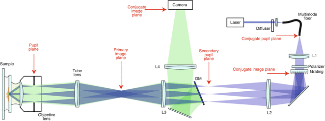
One way to generate the SIM excitation patterns is by using a diffraction grating and letting 2 (for 2D SIM) or 3 central diffraction orders (for 3D SIM) interfere at the sample plane. We have outlined such a possible setup in Fig. 5. A transmission phase grating is placed at a conjugate image plane in the illumination path. Laser light comes out of the end face of an optical fiber, is collimated by a lens (L1), and then diffracted by the grating. The diffracted beams are focused onto a secondary pupil plane by a relay lens (L2) and after passing through a dichromatic (or polychromatic) mirror are refocused onto the objective’s back focal plane by another relay lens (L3) and the tube lens (assuming an infinite conjugate objective lens is used). The spacing of the grating and focal lengths of the relay lenses are chosen such that the ±1 diffraction orders are located on the edge of the objective’s back focal plane. If TIRF is desired, care should be taken to place the beams in the region of the back focal plane that produces total internal reflection. The interference of 0 and ±1 diffraction orders (or only the ±1 orders in the case of 2D or TIRF SIM) at the sample space generates the sinusoidal excitation pattern used in SIM.


