The numerical aperture is dependent upon both the lens used and the refractive index (n) of the medium through which the light is transmitted:
(10.2)
where μ is the angle of the cone of light produced by the objective lens. It should be apparent that the resolving power of a light microscope is thus limited by the wavelength of visible light (which is why electron microscopies have much greater resolving powers, see below). It should also be clear that the resolving power can be increased by increasing the numerical aperture of the objective lens, which can be achieved by increasing the refractive index of the medium between the sample and the lens. Air has a refractive index of 1 and the maximum NA attainable is 0.95. If the medium is changed to a mineral oil, the maximum NA attainable is increased to 1.6. The maximum magnification attainable with a light microscope is of the order of ×1000.
One further consideration is depth of field (the distance in front of and behind the focal point that appears to be in focus). This will reduce with increasing magnification, which means that unless samples are quite thin, it can be difficult to get the whole sample into focus.
10.2.2 Hot-stage microscopy
A very important derivative of light microscopy is hot-stage microscopy (HSM). Here, a standard light microscope is fitted with a temperature-controlled stage, which means that the sample can be visualised as it is heated and cooled at a defined rate. Recall from Chapter 7 that DSC in particular is a very widely used tool in preformulation but that the data can be difficult to interpret in isolation. Visualisation of the changes occurring in a sample as a function of temperature is a powerful aid to interpretation of events seen in DSC thermal curves. It was noted earlier that operating HSM with cross-polarising filters was a particularly useful analytical method. This is because polymorphs are birefringent and so appear coloured. How is this so?
The wave model of light assumes vibration at right angles to the direction of propagation, with each vibration direction being equally probable. A plane-polarising filter allows only the light vibrating in one direction to pass through it. A cross-polarised light microscope contains two plane-polarising filters, one between the light source and the sample (the polariser) and the other between the sample and the ocular lens (the analyser). The filters are oriented at 90o to each other initially, although the operator can usually rotate the polariser. Ordinarily, then, this arrangement prevents transmission of any light from the source to the ocular lens. Crystalline materials are usually birefringent, which means the plane-polarised light is transformed into two wave components (the ordinary and extraordinary wavefronts) polarised in mutually perpendicular planes. The velocities of the wavefronts are different, and so out of phase, but they are recombined with constructive and deconstructive interference by the analyser, producing a coloured image. Different unit cells will interact with plane-polarised light to varying extents and so will produce patterns of different colours. Amorphous materials, conversely, are not birefringent and so do not orient plane-polarised light in any particular way, and appear black. This is a quick and useful check to determine whether a sample is amorphous.
While TGA can be used to quantify mass changes with temperature, these events can often also be seen with HSM. The sample is surrounded with a liquid in which it will not dissolve (usually a mineral or silicone oil) – any process that results in a gaseous degradant will be seen as a release of bubbles.
Study question 10.1 How might cross-polarised HSM be useful in interpreting DSC data?
10.2.3 Electron microscopy
From Equation (10.1) it can be seen that the resolving power of a microscope is dependent upon the wavelength of light used to illuminate the sample. Using a beam of electrons as the ‘light source’ greatly increases the resolving power of the microscope because the wavelength at which electrons travel in a vacuum is much shorter (ca. ×10 000 shorter). Electron beams cannot be focused with optical lenses, so electromagnets are used instead. Neither can they (nor should they) be visualised by eye, so fluorescent screens are used. Other than this change, the operating principles of electron microscopes are very similar to the light microscopes discussed above. As for light microscopes, electron microscopes can be operated in transmission (TEM) or reflectance (scanning or SEM) modes.
In TEM the electrons must pass through the sample and so the sample must be extremely thin. Typical applications include imaging nanoparticles, viruses and liposomes.
In SEM the electron beam is focused onto a 1–5 nm spot on the sample surface. The majority of electrons will pass through the sample but some interact with and are then emitted from atoms in the sample and are deflected back to the detector. These are known as backscattered or secondary electrons. The quality of the image is dependent upon the number of secondary electrons. To increase the number, samples are commonly covered in a heavy metal (such as gold) prior to imaging. Newer instruments do not operate under such a high vacuum and use a cascade of electrons generated from water molecules in the atmosphere to generate an image; these are called environmental SEM (ESEM) instruments. In either case, the electron beam is moved in an x–y direction across the sample surface in a raster pattern to construct the image.
10.2.4 Atomic force microscopy
Atomic force microscopy (AFM) works on completely different principles from the optical or electron microscopies described above. The principal part of an AFM is a small cantilever with a sharp tip. The cantilever is typically constructed from silicon or silicon nitride and the size of the tip is a few (1–10) nm. The size of the tip governs the image resolution. The tip is held in close proximity to the surface of the sample. On the top side of the cantilever is a small mirror, on to which a laser is aimed, the laser beam being deflected on to a detector.
In scanning mode, the cantilever is moved in an x–y direction across the surface of the sample in a raster pattern. As the topography (or surface roughness) of the sample changes, so does the height of the cantilever – movement in this z dimension changes the position of the laser beam on the detector, and so a topographical image of the sample surface can be constructed.
In tapping mode the cantilever is oscillated at or near to its resonance frequency by a small piezoelectric actuator (the amplitude of oscillation is typically 100–200 nm). As the tip nears the surface of the sample, forces of interaction (such as van der Waal’s forces, dipole–dipole interactions and electrostatic forces) change the amplitude of oscillation. An electronic servo uses the piezoelectric actuator to control the height of the cantilever above the sample and acts to maintain constant oscillation amplitude. A surface image can then be constructed by moving the cantilever in an x–y direction over the sample.
- Light and electron microscopies operate on similar principles, but electron microscopies have higher resolving powers because of the shorter wavelength of electron beams.
- Thin samples can be imaged in transmission mode.
- Thick samples are imaged in reflectance mode. Light microscopes suffer from a narrow depth of field.
- Atomic force microscopy uses the deflection of a cantilever to build up a topographical image of a sample surface.
10.3 Particle shape
10.3.1 Habit
It was noted in Chapter 7 that crystalline materials are defined as having a unit cell that repeats in three dimensions to produce the macroscopic crystal and that the gross exterior appearance of the crystal is called its habit. Six basic habits are listed in the USP (acicular (needle-shaped), blade, columnar, equant (equal-sided or isometric, including cubic and spherical), plate and tabular), although other terms are frequently encountered (such as hexagonal, octahedral, prismatic and pyramidal). Since the names are just descriptive terms for the macroscopic shape of the crystal and do not necessarily relate to the geometry of the unit cell, it can be difficult to identify polymorphic or pseudopolymorphic forms by image analysis alone. However, knowledge of habit is important, because particle shape can affect processability (influencing factors such as compressibility, flowability, mixing and filtration). Similarly, particle size is often critical to drug product performance and habit can change as the crystal grows in solution.
Since the molecules in a crystal lattice are all arranged in the same orientation, it follows that different faces of a crystal will have different properties (since different functional groups will be exposed at each face), such as surface energy, polarity or chemical reactivity. Further, because crystals grow by condensation of molecules (from the melt or from solution) it may well be the case that condensation is more favoured on certain faces and less favoured on others, with the outcome that the crystal may grow preferentially in certain directions (anisotrophy).
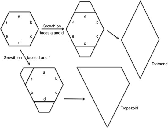
The effect of preferential growth on certain faces of the crystal is manifest in changes in habit. Figure 10.1 shows what will happen to a hexagonal seed crystal if growth occurs on different faces. When growth occurs on faces a and d the final habit is a diamond, while when growth occurs on faces d and f the final habit is a trapezoid. This is why simply observing the crystal habit does not allow assignment of a unit cell structure. Note here that those faces upon which crystal growth is preferred eventually disappear while at the same time those faces upon which growth is less favoured become larger. The net result is that the largest face is always the slowest growing.
< div class='tao-gold-member'>