Fig. 1
CMR-acquisition protocol and offline segmentation: a positioning of LV long-axis of acquisition; b derived rotational sequence of acquisition consisting of 18 long-axis planes; c view of the segmentation panel with a tracking example of MV apparatus
At this aim, a computational FE strategy, based on in vivo CMR data, is presented herein to deeper investigate MV prolapse repair through implantation of ePTFEneochordae: the developed approach focuses on MV leaflets repositioning, chordal tension redistribution and tissue stresses assessment after MV repair.
2 Methods
An integrated framework was developed combining CMR technology, FE methods and the use of dedicated software packages: the developed analysis allows the quantitative assessment of MV apparatus and the simulation of different NCI techniques as detailed in the following paragraphs.
2.1 CMR Acquisition and Image Segmentation
Cardiac Magnetic Resonance (CMR) was performed on a male patient (75 years old, 83 kg, 168 cm) who underwent surgery for isolated prolapse of mitral posterior P2 scallop due to multiple rupture of marginal chordae. A customized sequence of acquisition was carried out on a 3.0T TX Achieva (Philips Medical System, Irvine, Calif) machine: cine-images were obtained through 18 long-axis planes, evenly rotated along the left ventricle (LV) axis every 10 degrees, with an isotropic pixel spacing, stored in each DICOM image file as the distance between adjacent pixels, of 1.25 mm and a slice thickness of 8 mm. Using a breath-holding modality, 30 cardiac phases were recorded on each plane, with different temporal resolution according to the characteristic R-R interval of each patient.
The use of a CMR rotational sequence of acquisition allowed to completely acquire MV apparatus and dynamically assess its function through out an entire cardiac cycle. The axis of rotation coincided with LV axis and it was defined as the segment connecting LV apex and mitral valve centroid (as schematically reported in Fig. 1a: both points were identified through auxiliary CMR short-axis planes and LV axis was finally arranged after checking the operation on a supplementary LV long-axis plane. For each acquisition, a set of 540 DICOM images were generated and a total acquisition time of about 10 min was required.
Offline CMR images segmentation was performed using a dedicated software [12] developed in MATLAB (The MathWorks Inc., Natick, Mass). As detailed in Fig. 1c, two points (in red color) were manually selected on MV annulus in each of the acquired plane, two points (in yellow color) were positioned on the free margin of the MV leaflets and each papillary muscle (PM), where visible, was added through a variable number of points (green points). Three-dimensional coordinates were then computed using the information stored in the appropriate DICOM fields.
Mitral annular geometry was automatically generated through a 4th order Fourier approximating function fitting the selected annular points; both anterolateral and posteromedial PMs were positioned in the 3D space applying a K-means partitioning algorithm to separate reference points in two mutually exclusive clusters and identifying the centroid of each PM tip. An additional set of points, was positioned on the long-axis profile of each MV leaflet in order to derive MV leaflet profile through a polynomial fitting (green lines), its local inclination (with respect to acquisition axis) and leaflet extension, i.e. the distance between annulus and leaflet free-margin.
The segmentation of CMR images provided MV end-diastolic configuration and the kinematic boundary conditions representing annular and PMs dynamics. In addition, MV leaflet surface was assessable at systolic peak, i.e. the mid-frame of systolic interval within the set of CMR-phases, in order to reproduce MV morphology and the severity of leaflet dysfunction through the extraction of different morphological variables (e.g. leaflet billowing height and volume, regurgitation area, prolapse extension, etc.).
2.2 Finite Element MV Pre-operative Model
Structural patient-specific FE models were derived from the CMR-extracted morphology and integrated with intra-operative findings, in order to reliably reproduce the specific MVP pattern; data from the literature were used to describe the mechanical properties of leaflets, chordae tendineae and, in particular, artificial ePTFE sutures. Once a pre-operative model (with chordal rupture) was simulated, the potential outcomes of neochordal implantation (NCI) were assessed, evaluating different suture configurations. All simulations were carried out using the commercial solver ABAQUS Explicit 6.10 (SIMULIA, Dassault Systèmes, Providence, RI).
MV leaflets were characterized by a single anterior segment and the peculiar division of the posterior leaflet in three different scallops (i.e. P1, P2 and P3, respectively): the end-diastolic geometry was discretized with a homemade software written in Python (Python Software Foundation, Beaverton, OR): the mesh consisted of 3-nodes shell elements (ABAQUS S3R element type) and a mapped scheme of meshing was adopted. The number and the distribution of chordae tendineae were defined according to a paradigmatic scheme [12] derived from ex vivo findings [13, 14] and it included all MV characteristic types of chordae tendinae: marginal (first order), basal (second order) and structural anterior chordae.
As above mentioned, in order to reproduce a reliable pre-operative model, structural FE models were integrated with intra-operative measurements and surgical findings, thus confirming location and extent of the prolapsing region and the exact number and type of ruptured chordae.
All tissues were assumed as homogeneous (1.1 g/cm , non-linear and elastic: their behaviour was modeled on the basis of the hyperelasticity theoretical framework in order to account for their large deformations.
, non-linear and elastic: their behaviour was modeled on the basis of the hyperelasticity theoretical framework in order to account for their large deformations.MV leaflet response was described through the hyperelastic constitutive model originally proposed by May-Newman et al. [15], which is based on the strain energy function  that depends on two invariant measures of finite strain I
 and I
and I :
:
![$$\begin{aligned} \Psi (I_1, I_4)=c_0\left[ e^{c_{1}(I_1-3)^2+c_2(\sqrt{I_4}-1)^4}-1\right] \end{aligned}$$](/wp-content/uploads/2016/10/A324942_1_En_8_Chapter_Equ1.gif)
where  and
and  , in which
  is the right Cauchy-Green tensor,
  is the unit vector which defines the preferential direction of the fibers in the material in the undeformed shape and
  is the stretch of the fibers in the
  direction.
  is the deformation gradient tensor, defined as
  , i.e. the derivative of the current position with respect to the undeformed position. The constitutive relation was implemented in a user-defined subroutine (VUMAT), as detailed in [12]: the constitutive parameters identified by May-Newman were used [15] and, accordingly, the direction parallel to the annular profile was defined as the preferential direction of the collagen fibers. Moreover, regionally varying thicknesses were assigned to the anterior and posterior MV leaflets as reported in [16].
that depends on two invariant measures of finite strain I and I:(1)
and , in which is the right Cauchy-Green tensor, is the unit vector which defines the preferential direction of the fibers in the material in the undeformed shape and is the stretch of the fibers in the direction. is the deformation gradient tensor, defined as , i.e. the derivative of the current position with respect to the undeformed position. The constitutive relation was implemented in a user-defined subroutine (VUMAT), as detailed in [12]: the constitutive parameters identified by May-Newman were used [15] and, accordingly, the direction parallel to the annular profile was defined as the preferential direction of the collagen fibers. Moreover, regionally varying thicknesses were assigned to the anterior and posterior MV leaflets as reported in [16].Native chordae tendineae response was assumed isotropic and described through hyperelastic models available in ABAQUS/Explicit and fitting data from literature [17] through a 2nd order polynomial function for marginal and structural chordae and a 5th order Ogden function for basal chordae.
For each patient-specific model, two simulations were preliminary implemented: the former represented the pre-operative model (Pre-Op model) reproducing the clinical scenario of MV lesions and prolapse dysfunction as derived from CMR images; the latter, replicating the same geometry of Pre-Op model, represented the physiological MV model (Phy model) without prolapse, i.e. with a complete and intact chordal apparatus with respect to pre-operative conditions. For both models, the systolic MV biomechanics was simulated, applying a physiological pressure load to the leaflets, for a total simulation time of one second. As above mentioned, boundary conditions were extracted from CMR-segmentation and reproduced annular kinematics and PMs displacement. A general contact algorithm, available in ABAQUS with a scale-penalty method and a friction coefficient of 0.05 was used to model MV leaflets coaptation [18].
2.3 Neochordal Implantation (NCI)
Expanded polytetrafluoroethylene (ePTFE) CV-5 neochordae were modeled as non-linear springs (ABAQUS SPRINGA elements) with no resistance to compression and a diameter of 350  m as reported by the manufacturer: force-elongation behavior was derived from literature data [19] consistently with neochordae undeformed length and cross-section, and the characteristic stress-strain curve of the material (Fig. 2a).
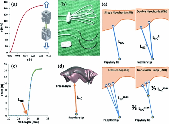
m as reported by the manufacturer: force-elongation behavior was derived from literature data [19] consistently with neochordae undeformed length and cross-section, and the characteristic stress-strain curve of the material (Fig. 2a).Fig. 2
a Stress-strain curve of ePTFE CV-5 sutures as derived from monoaxial traction tests available in literature [19]; b typical single and loop configurations of artificial neochordae for MVP repair; c computational force-elongation behavior defined for a single ePTFE artificial neochorda with an undeformed length of 24 mm; d simulation of the measurement of neochordal length, in the Phy model: the distance between the leaflet free margin and the corresponding PM tip was used; e schematic representation of the performed NCIs
Subsequently, different clinical NCI procedures were simulated (as schematically reported in Fig. 2e) and the proper suture length was determined, for each NC configuration, as follows:
1.


single neochorda (SN) with suture length  approximated in millimeters to the distance, measured in Phy model at peak systole, between PM tip and the selected point of neochordal insertion along the free margin of the MV scallop;
approximated in millimeters to the distance, measured in Phy model at peak systole, between PM tip and the selected point of neochordal insertion along the free margin of the MV scallop;Stay updated, free articles. Join our Telegram channel
Full access? Get Clinical Tree
