(1)

(2)

(3)
Heart radii | Vertical long axis  (mm) (mm) | Short axis plane  (mm) (mm) |
|---|---|---|
End diastolic | 49.7 | 25.1 |
End systolic | 45.7 | 21.3 |
Mean value (preformed) | 47.7 | 23.2 |
With these, a circular plate can be deformed into a double curved shape as shown in Fig. 1. This represents a simplified model of a myocardium, whereby heart movement is simulated through changes between the radii of end diastolic and end systolic state.
2.1.2 Element Type
Simulations were performed with the commercial code Abaqus/CAE (Dassault Systèmes Simulia Corp., RI, USA). Abaqus offers different element types for structural problems. Since the response of the scaffolds are bending dominated special elements had to be selected. Standard linear hexahedral elements appear to be inappropriate; instead the linear formulation with incompatible mode was used (C3D8I) which yields accurate displacement and stress fields. In a test case four elements were used over the thickness to compare the finite element solution to an analytical solution of a clamped beam. Stress was normalized to the analytical solution and calculated to be 0.982 at the fixed support (C3D8I). For quadratic hexahedral elements, normalized stress was determined to be 0.995, and is equal for reduced and full integration formulations (C3D20R and C3D20). Increasing the element quantity about eight times (C3D8I  0.991; C3D20R & C3D20
  0.999) and also about 35 times (C3D8I
  0.995; C3D20R & C3D20
  1) lead to minor improvements in accuracy. Evaluating the normalized tip displacement gives similar results. Since linear elements are less costly in calculations and the element C3D8I has a comparable accuracy to quadratic element types, the linear type is preferable. Furthermore, complex structures can be discretized with a finer mesh without extending the calculation time using linear elements as compared with quadratic elements.
 0.991; C3D20R & C3D20
  0.999) and also about 35 times (C3D8I
  0.995; C3D20R & C3D20
  1) lead to minor improvements in accuracy. Evaluating the normalized tip displacement gives similar results. Since linear elements are less costly in calculations and the element C3D8I has a comparable accuracy to quadratic element types, the linear type is preferable. Furthermore, complex structures can be discretized with a finer mesh without extending the calculation time using linear elements as compared with quadratic elements.
2.1.3 Assembly
Two scenarios were considered: a surgeon manually deforming a flat scaffold according to the heart curvature and an already preformed scaffold sewn onto the myocardium. These modeling ideas were briefly introduced by Bauer et al. but are presented here in more detail [25].
The scaffold is positioned onto the myocardium and single nodes are constrained to avoid its translation and rotation, as shown in Fig. 2a. It is assumed that surgeons use their thumbs to deform the scaffold; therefore, thumb models are positioned onto the scaffold (Fig. 2b). ‘Thumbs’ are modeled to be equidistant and perpendicular to the myocardium. The scaffold is deformed in two steps as displayed in Fig. 2c, d.
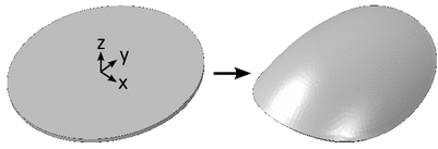

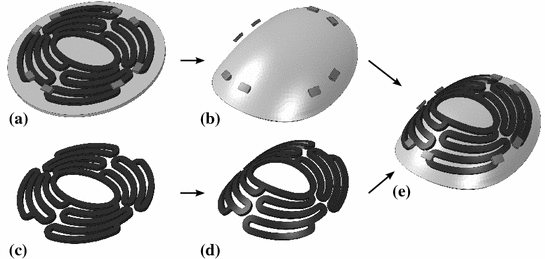

Fig. 1
Modeling of myocardium by deforming a plate according to the heart curvature

Fig. 2
Modeling of flat scaffold: a Positioning of flat scaffold on plate, nodes A are constrained in y-direction and node B is constraint in x-direction; b positioning of thumbs onto scaffold; c and d deforming flat scaffold into heart curvature in two steps

Fig. 3
Modeling of preformed scaffold: a positioning of sutures onto flat scaffold; b preforming of myocardium with sutures; c and d deforming flat scaffold into preformed state; e assembling of orphan-meshes of scaffold, myocardium and sutures in preformed state
Preformed scaffolds can be designed with CAD2-programs and imported into finite element (FE) software. However, it is costly to mesh curved, complex geometries with hexahedral elements; furthermore, positioning of sutures is challenging. Therefore, another method was chosen. In flat state, sutures were positioned on the scaffold according to their locations in surgeries (Fig. 3a). Sutures were simplified as half cylinders. They restrain their position relative to the myocardium during heart movement. The myocardium with sutures was deformed into the preformed state (see Table 1) as shown in Fig. 3b. In the second step, the scaffold was also deformed into the preformed shape (Fig. 3c, d). The preformed meshes are imported as orphan-mesh into a second model (Fig. 3e). Orphan-meshes contain no history data; therefore, they are stress free, comparable to a preformed structure after heat treatment. The heart movement of the preformed myocardium is modeled using the displacements in Eqs. (1–3), but it is necessary to calculate the displacement differences from one curvature state to the other.
2.1.4 Parameters
The magnesium alloy LA63 is not commercially available. Its properties were determined through tensile testing, and found to be: Young’s modulus of 46,068 MPa and Poission’s ratio of 0.28. Nonlinear material parameters are given in Table 2; isotropic hardening was assumed. Myocardium and sutures as well as thumbs were assumed to be linearly elastic and isotropic, Young’s moduli were chosen as 66 MPa [27] and 1,300 MPa, for the myocardium and sutures (thumbs), respectively.
Surface-to-surface contact was defined between interacting bodies, and frictionless contact was assumed. The penalty method was used as contact algorithm with a stiffness scale factor of 0.01.
True stress (MPa) | 137 | 150 | 174 | 187 | 197 |
True plastic strain | 0.0000 | 0.0020 | 0.0107 | 0.0182 | 0.0263 |
Components were meshed with linear hexahedral elements with incompatible modes (C3D8I). A sensitivity analysis was performed to choose an appropriate mesh size. Accordingly, the model of the preformed scaffold was meshed with different refinements. Von Mises stresses were determined at five points and compared to the element sizes as shown in Fig. 4. Further, the computing time was contrasted. Stress changes were observed at points 1 and 2, while all other locations were unaffected. These two points are in or close to tight radii where higher stress concentrations can be assumed; therefore a higher sensitivity to the mesh size is observed. An element size of ‘ ’ was chosen in order to adequately account for sharp corners and complex geometries while still maintaining a reasonable computing time. Therefore, a 1 mm thick scaffold was meshed with an element edge size of 0.2 mm and six elements in thickness.
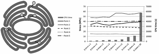
 ’ was chosen in order to adequately account for sharp corners and complex geometries while still maintaining a reasonable computing time. Therefore, a 1 mm thick scaffold was meshed with an element edge size of 0.2 mm and six elements in thickness.
Fig. 4
Sensitivity study on mesh refinements and resultant stress in five points
2.1.5 Simulations
In the first simulation the response of a flat 1 mm thick scaffold was investigated that is deformed by a surgeon to match the shape of the heart curvature before it is sewn onto the myocardium. For this the ‘thumb’-model from Fig. 2 was used and the myocardium was deformed into the preformed state. The second simulation examined the behavior of a preoperative preformed scaffold (stress free) that is deformed from preformed to end diastolic to end systolic state. This simulation of one heart movement cycle was performed for scaffolds of 0.5 mm and 1 mm thickness.
2.2 Modeling Results
The flat scaffold was deformed in two steps by thumbs and then kept in a position equivalent to the preformed state. Relatively high stresses occurred in the scaffold, as can be seen in Fig. 5. The yield point of 137 MPa was exceeded in several areas. Furthermore, stresses above the ultimate tensile strength of 197 MPa were determined for a few locations. Stresses beyond the yield point indicate plastic deformations, which are displayed in Fig. 5. The plastic strain that corresponds to the ultimate tensile strength was determined to be 2.6 %. This value was used as scale limit; therefore, strains exceeding it are plotted in red in Fig. 5. Areas stressed and strained above the point of ultimate tensile strength are susceptible to material overload, therefore material failure is likely. Further, plastic strains during cyclic loading can lead to fatigue.
The stress distribution of preformed scaffolds, deformed into end diastolic and into end systolic state, is shown in Fig. 6. Compared to the flat scaffold, calculated stresses were much lower. Maximal stress in the 0.5 mm thick scaffold was determined to be 26 MPa and 59 MPa for the end diastolic and end systolic states, respectively. For the 1 mm thick scaffold maximal stress was higher: 45 MPa in end diastolic and 96 MPa in end systolic state. No plastic strains were observed.
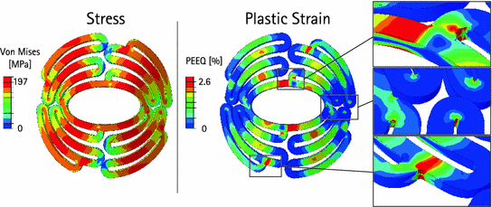
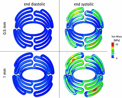

Fig. 5
Distribution of stresses and plastic strains within a 1 mm thick flat scaffold deformed into preformed state

Fig. 6
Stress distribution in end diastolic and in end systolic state for 0.5 mm and 1 mm thick preformed scaffolds
From these results, it can be concluded that it is advisable to use initially preformed scaffolds instead of flat ones. Material stresses in flat scaffolds are quite high and early failures due to fatigue are very likely. Therefore, only preformed scaffolds were considered in following simulations.
3 Developing of New Scaffold Shapes
3.1 Improving Scaffold Shapes and Introducing New Designs
3.1.1 Model Extension
Previously presented simulations correlate to the situation outlined by Schilling et al. where the scaffold is sewn onto the epicardium [24]. However, it is intended that the scaffold protect a biological graft against bulging. Therefore, the resulting load on the scaffold due to swelling of the graft must be taken into account. Since no material data of an appropriate tissue was available, another approach was chosen. It was assumed that a bulging graft induced a pressure onto the scaffold. Pressure peaks of up to 240 mmHg are possible in the left ventricle. For the simulation, 140 mmHg was chosen—representing prehypertension— and applied onto the back of the scaffold in the systolic step [28]. With this approach, calculations were performed for scaffolds of 0.5 mm and 1 mm thickness.
3.1.2 Design Requirements
Manufacturing techniques, operating site, and intended purpose of an implant define its design requirements. The implant is for use on the myocardium, while its size depends on the size of the damaged area. Diameters of 30–60 mm seem to be typical; we chose an outer diameter of 40 mm. An opening, preferably in the middle of the scaffold, is needed to allow the passage of vessels for blood supply. The intention of the scaffold is to support a biological graft and prevent it from bulging [22]. Therefore, a high contact area between graft and implant is needed, the heart movement should not be restricted, and the scaffold should withstand the cardiac motion. Sheets down to a thickness of 0.5 mm can be manufactured from LA63. The scaffold should have strut widths of at least 1 mm. Spaces between the struts may be a minimum of 0.6 mm due to the cutting diameter of the abrasive waterjet cutting method used to form the scaffolds [29].
3.1.3 Shape Improvements
Under pure bending, a reduction of structure thickness will lead to lower maximal stress. This effect was already investigated (see Fig. 6). Further, it is possible to locally decrease the thickness where high bending stresses are detected and thereby introduce a kind of ‘hinge’. However, this approach increases the manufacturing expense and is not advocated. A uniform structure thickness was chosen, with stresses reduced by changing the structure shape.
Stay updated, free articles. Join our Telegram channel

Full access? Get Clinical Tree


