Fig. 1
Respiratory mechanics: the role of the diaphragm and thorax in breathing
The diaphragm moves down during the inhalation, creating negative pressure around the thoracic cavity and decreasing pressure on abdominal organs. As it moves up during exhalation, the pressure increases on the lungs and on abdominal organs (Fig. 1). Lungs are linked to the diaphragm and to the ribs through the pleura. The pleura consists of two sheets (visceral and parietal). The visceral pleura is attached to the lungs and the parietal pleura is attached to the diaphragm and to the chest wall. Between the two sheets, an incompressible fluid allows lungs to slide while they follow diaphragm and ribs motion.
2.2 3D Automatic and Semi-Automatic Segmentation
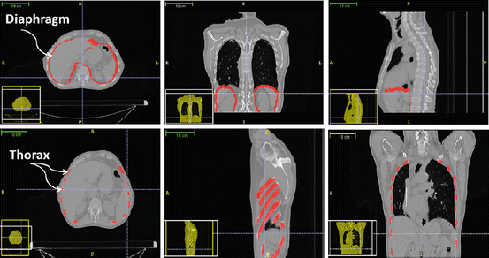
We have chosen CT scan data covering the whole thorax of a patient. The 4D CT set is issued from a pre-treatment procedure of a lung cancer patient. From the 4D set, we choose two 3D sets of images that correspond to the maximum and to the minimum of the respiratory cycle. The diaphragm is a thin tissue, with thickness between 2 and 5 mm. In Fig. 2, the diaphragm was segmented semi-automatically using the snake evolution methodology available in the ITK-SNAP library. The diaphragm muscles and tendon may not be identified separately on CT images. According to [13], the mean central tendon surface area is 143 cm2. This area does not vary to a large extent from one person to another.


Fig. 2
Automatic and semi-automatic segmentation of the internal organs of the respiratory system: ribs, human diaphragm, and lungs
An automatic segmentation algorithm of the thorax with all musculoskeletal structure was developed in our team. We have applied a threshold value to the images and used morphological operators in order to fill holes and link separated regions that correspond to the same rib. Then, a surface mesh of the ribs and spine was generated using the marching tetrahedron algorithm.
2.3 Patient-Specific Anatomical 3D Model
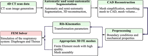
Figure 3 presents a global methodology pipeline in order to generate biomechanical patient-specific anatomical 3D models of the respiratory system from medical images. The main motivations of the proposed methodology pipeline based on CAD-modeling come from the difficulties in applying the finite element (FE) method in biomechanical analysis due to the complexity associated with creating subject-specific anatomical models. For this reason we have adopted the following computational procedure:


1.
4D CT scan images; acquisition and generation of the 4D CT images of the whole respiratory system,
2.
3D automatic and semi-automatic segmentation, 3D reconstruction of the respiratory system (different organs),
3.
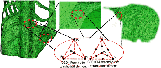
3D CAD model reconstruction and then 3D mesh generation from CT images (decimation, smoothing, etc.) in order to generate the appropriate mesh elements adapted to finite element simulation, (Fig. 4)
4.
Boundary conditions between the various organs of the respiratory system (lungs, diaphragm, thorax, etc.) based on anatomical and physiological properties,
5.
Finite element analysis of the respiratory system based on appropriate behavior laws for each organ (linear elastic, nonlinear hyperplastic, homogenous or heterogenous, etc.).

Fig. 3
Global pipeline in order to generate patient-specific anatomical 3D models of the respiratory system from medical images (CT scan data) to finite element simulation

Fig. 4
Representation of the 3D diaphragm and thorax meshes
2.4 Generation of the Finite Element Mesh
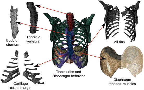
Mesh generation is a critical and important step in the finite element analysis process. The mesh affects the accuracy, convergence, and speed of the computational process: a more precise and efficient finite element mesh will result in a more accurate and faster solution. Suitable geometry simplification plays a major role in obtaining a proper finite element model for a specific application. Simplifications usually involve elimination of less important details that unnecessarily increase the meshing complexity. In this order, it is necessary to obtain a high quality 3D geometrical representation of anatomical shapes and generate adapted FEM meshes. For the geometries, we have used NURBS surface models, resulting in non-intersecting and smooth organ representations (Fig. 5).


Fig. 5
Different parts of the human diaphragm and thorax including: tendon and muscles tissues, ribs, thoracic vertebra, costal cartilage margin, body of sternum
2.5 Respiratory Biomechanics
Finite element simulations are performed by using Abaqus.1 In this study, we chose two simple hyperelastic models: Saint-Venant Kirchhoff and Mooney–Rivlin.
For an isotropic elastic or hyperelastic material, the elastic energy, noted W, may be written as:

where E is the Green–Lagrange strain tensor, λ and μ are the Lame coefficients. As the strain energy function W is quadratic in terms of strain invariants, we obtain a linear relation between the second Piola–Kirchhoff stress tensor and the Green–Lagrange strain tensor given by:

The strain energy of the second hyperelastic Mooney–Rivlin model may be written as:

where c 1, c 2 are material parameters and K is the Bulk modulus. The quantities  and
and  are the isochoric invariants of the Cauchy-deformation tensor
  :
:  ,
,  where
where  ,
,  and J is the Jacobian:
  .
.

(1)

(2)

(3)
 and
and  are the isochoric invariants of the Cauchy-deformation tensor
  :
:  ,
,  where
where  ,
,  and J is the Jacobian:
  .
.2.6 Rib Cage and Intercostal Muscles: Rib Kinematics
The diaphragm biomechanics model is coupled with rib kinematics, with the aim to establish a thoracic model that may be monitored by external parameters. We have developed two different methods:
a “direct” method allowing to compute the skin position from the ribs motion.
an “inverse” method providing rib motion and consequently lung motion. It may be computed from the outer surface motion.
In this chapter, we focus on the first approach. The direct model describes the motion of the ribcage based on particular rigid transformations computed with the finite helical axis (FHA) method applied to each rib, which describes movement as a rotation and a translation along a single axis in the 3D space.
A state-of-the-art methodology to study human rib displacements using the FHAM is presented in our work [14, 15]. Since ribs may be considered as rigid bodies in comparison with other surrounding anatomical elements, each rib transformation parameter is computed automatically between the initial and final states of the respiratory motion (Fig. 6).


