FIGURE 20-1 Electroanatomic voltage maps in a 33-year-old man with nonischemic idiopathic dilated cardiomyopathy.
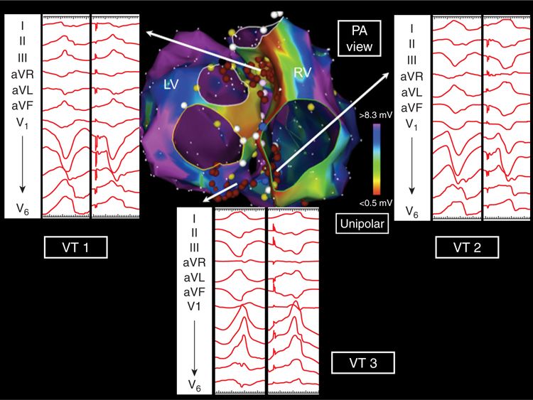
FIGURE 20-2 Posteroanterior projection of unipolar biventricular voltage maps showing periannular septal and infundibular substrate. The three inducible VTs were pace-mapped to this region where radiofrequency ablation rendered them noninducible.
CASE EXPLANATION
Catheter ablation of scar-related VT is often beset by the problem of multiple poorly tolerated, unstable VT morphologies that cannot be defined by entrainment mapping. These unmappable VTs need to be targeted in sinus rhythm, and their critical circuit components are invariably located in zones of fibrosis. The various forms of structural heart disease that cause scar-related VT usually display confluent areas of myocardial surface fibrosis. This involves the endocardium in ischemic (postinfarct) cardiomyopathy or the epicardium in arrhythmogenic right ventricular dysplasia. The various forms of nonischemic dilated cardiomyopathy (DCM) are characterized by diffuse interstitial and replacement fibrosis, and this may result in a basolateral, predominantly epicardial pattern scarring. However, the normal endocardial and epicardial bipolar surface voltage maps in a VT patient with DCM strongly suggested the presence of intramural substrate. Unipolar electrograms have a wider “field-of-view” and may be sensitive to deeper layers of fibrosis within the myocardium. In this case, substrate mapping disclosed the presence of unipolar low voltage on basal septum, suggestive of intramural scarring that corresponded to the DGE-defined fibrosis seen with MRI.
VENTRICULAR ELECTROGRAM RECORDING AND DEFINITIONS
Contact intracardiac electrograms are recorded from the ventricles by placing the distal recording electrodes of a mapping catheter at sequential endocardial or epicardial sites. Typical mapping catheters in current use employ a 3.5-mm distal tip electrode, a 2-mm ring electrode on the shaft, with a 1-mm interelectrode spacing. Unipolar electrograms can be recorded from each of these two electrodes using either Wilson’s central terminal or an indifferent electrode in the inferior vena cava. Bipolar electrograms are recorded between the tip and ring electrodes by vector summation of their individual unipolar signals. The signals are digitized and amplified and then subject to high and low pass filtration to remove the effects of low-frequency respiratory noise and high-frequency electrical noise from the final processed electrogram.
Cassidy et al found that normal ventricular bipolar electrograms recorded from healthy myocardial tissue (with a 10-mm bipole, filtered at 30-500 Hz) exhibit characteristic properties (Figure 20-3A). They have sharp, biphasic, or triphasic deflections with peak-to-peak amplitude ≥3 mV, duration <70 ms, and/or amplitude:duration ratio >0.045.5 As they are acquired, normal and abnormal electrograms can be plotted onto color-coded three-dimensional voltage maps using an electroanatomic mapping system.
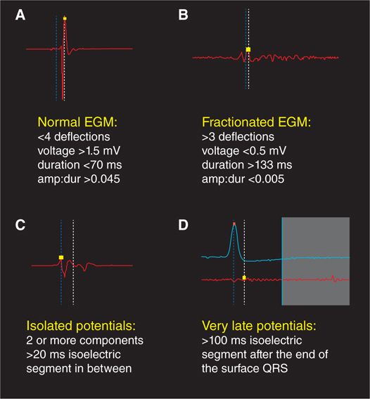
FIGURE 20-3 Characteristics of normal, fractionated, isolated, and very late ventricular electrograms.
All forms of ventricular scarring cause disruption to the normal myocardial syncytial architecture, variably replacing necrotic or apoptotic cardiomyocytes with collagen. In dense sheets of scar, surviving myocyte bundles may be present with abnormally slow and circuitous electrical activation due to the insulating effects of confluent fibrotic zones as well as the loss of normal cell-to-cell coupling. This slow conduction can be also caused by more diffuse interstitial and replacement fibrosis. In either case, electrograms recorded from such regions display reduced peak-to-peak amplitude due to lesser action potential summation from the lower surviving myocyte mass. Additionally, the slow conduction caused by shards of fibrosis results in electrogram prolongation, with multiple deflections commonly seen due to adjacent myocyte bundles being sequentially activated in delayed fashion, rather than rapidly in parallel. These electrogram changes are known as fractionation, and fractioned ventricular electrograms display multiple deflections from baseline, an amplitude ≤0.5 mV, a duration ≥133 ms, and/or amplitude:duration ratio <0.005 (Figure 20-3B). If delayed conduction occurs into surviving myocyte bundles that are well insulted by surrounding collagen sheets, late components of the local electrogram may be inscribed at a discernible interval (with an isoelectric duration of >20 ms) after the initial electrogram component, which is usually a far-field signal (Figure 20-3C). In very slow conduction regions, these potentials may occur well after the surface QRS complex (Figure 20-3D). These are known variably as late potentials (LP) or isolated late potentials (ILP) and likely represent depolarization of anatomically constrained surviving fiber bundles within dense sheets of scar.6 Local abnormal ventricular activities (LAVA) is another term used to describe similar electrogram abnormalities within scar.7
BIPOLAR ENDOCARDIAL VOLTAGE MAPPING
Stay updated, free articles. Join our Telegram channel

Full access? Get Clinical Tree


