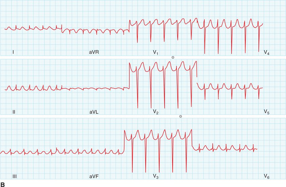
FIGURE 43-1 (A) A 12-lead ECG recorded during typical AFL, with typical saw-toothed pattern of inverted F waves in the inferior leads II, III, and aVF. (B) A 12-lead ECG recorded during reverse typical AFL, with atypical F wave pattern in the inferior leads. (Reproduced with permission from Feld GK, Srivatsa U, Hoppe B. Ablation of isthmus dependent atrial flutters. In: Huang SS, Wood MA, eds. Catheter Ablation of Cardiac Arrhythmias. Philadelphia, PA: Elsevier; 2011.)
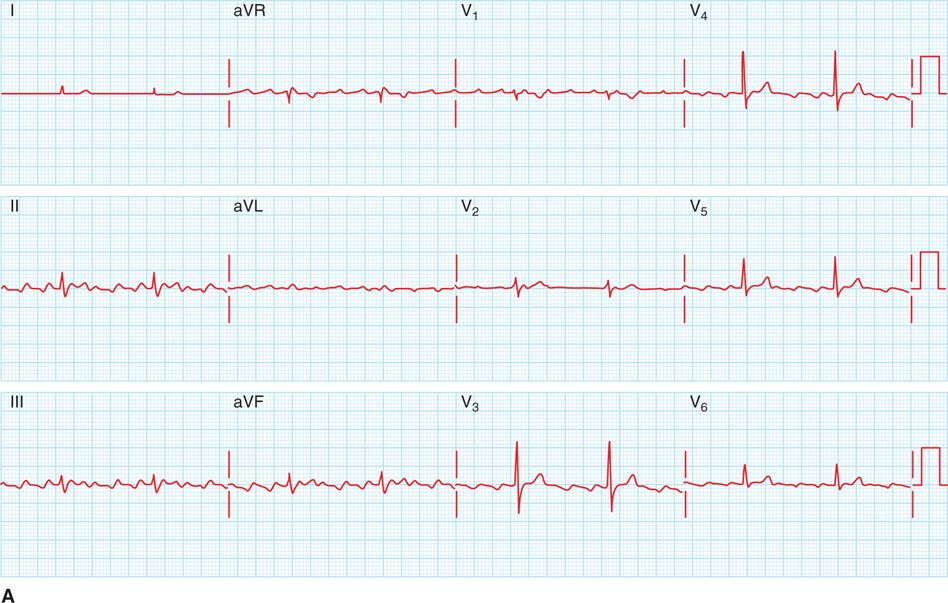
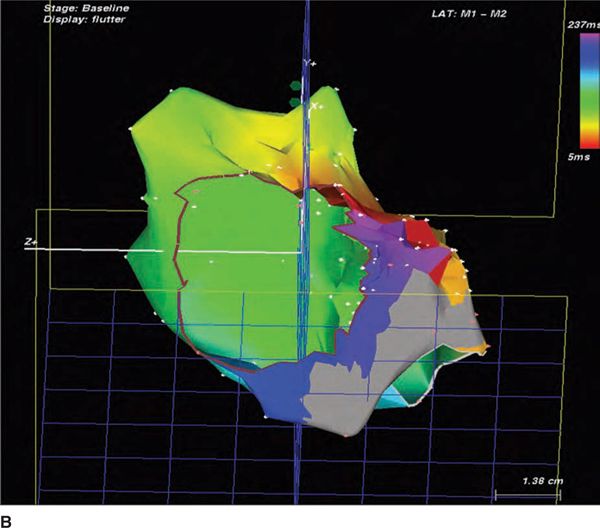
FIGURE 43-2 (A) A 12-lead ECG recorded during AFL following initial CTI ablation attempt. Note the biphasic F waves in the inferior leads II, III, and aVF, an atypical AFL pattern suggesting possible non–isthmus-dependent AFL. (B) During EPS a CARTO map of induced atrial flutter demonstrates an area of scarring (grey area) throughout the CTI near the Eustachian ridge, but continued activation of the CTI near the tricuspid valve annulus in a counterclockwise direction producing typical AFL. Color red = earliest activation, color purple = latest activation, reference coronary sinus electrogram. [(B) Reproduced with permission from Feld GK, Birgersdotter-Green U, Narayan S. Diagnosis and ablation of typical and reverse typical (type 1) atrial flutter. In: Wilber D, Packer D, Stevenson W, eds. Catheter Ablation of Cardiac Arrhythmias: Basic Concepts and Clinical Applications. 3rd ed. Oxford, England: Blackwell Publishing; 2007:173-192.]
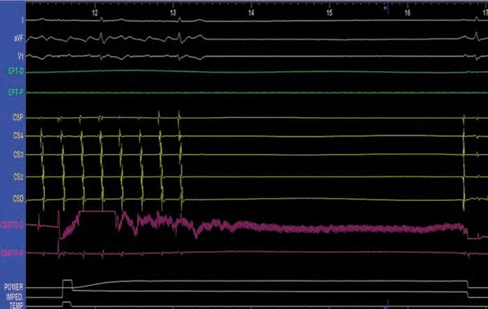
FIGURE 43-3 Surface ECG leads I, aVF, and V1 and endocardial electrograms from the coronary sinus catheter (CSP-D), the ablation catheter (CARTO P&D), and power, impedance, and temperature readouts, show termination of AFL and restoration of sinus rhythm immediately after initiating ablation near the tricuspid valve annulus.
ELECTROPHYSIOLOGIC MECHANISMS OF ISTHMUS-DEPENDENT (TYPICAL AND REVERSE TYPICAL) ATRIAL FLUTTER
Electrophysiologic studies have shown typical and reverse typical AFL to be due to counterclockwise (typical) or clockwise (reverse typical) macroreentry around the tricuspid valve annulus (Figure 43-4, left and right), with an area of slow conduction in the CTI accounting for one-third to one-half of the AFL cycle length.1–10 The CTI is bounded by the inferior vena cava and Eustachian ridge posteriorly and the tricuspid valve annulus (TVA) anteriorly (see Figure 43-4, left and right), forming barriers delineating a protected zone in the reentry circuit.5,11–13 Lines of block, including the Eustachian ridge and the crista terminalis, along which double potentials are typically recorded during AFL (Figure 43-5A and B), are necessary to establish an adequate path-length for reentry to be sustained and to prevent short circuiting of the reentrant circuit.12–14
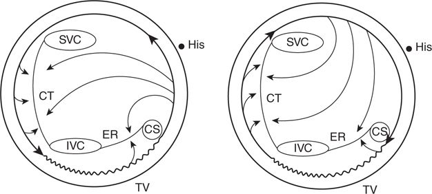
FIGURE 43-4 Schematic diagrams demonstrating right atrial activation patterns in typical (left) and reverse typical (right) forms of CTI-dependent AFL. In typical AFL, reentry occurs in a counterclockwise direction around the tricuspid valve annulus (TVA), whereas in reverse typical AFL reentry is clockwise. The Eustachian ridge (ER) and crista terminalis (CT) form lines of block, and an area of slow conduction (wavy line) is present in the CTI between the inferior vena cava (IVC) and Eustachian ridge and the tricuspid valve annulus. Abbreviations: CS, coronary sinus ostium; His, His bundle, SVC, superior vena cava. (Reproduced with permission from Feld GK, Srivatsa U, Hoppe B. Ablation of isthmus dependent atrial flutters. In: Huang SS, Wood MA, eds. Catheter Ablation of Cardiac Arrhythmias. Philadelphia: Elsevier; 2011.)
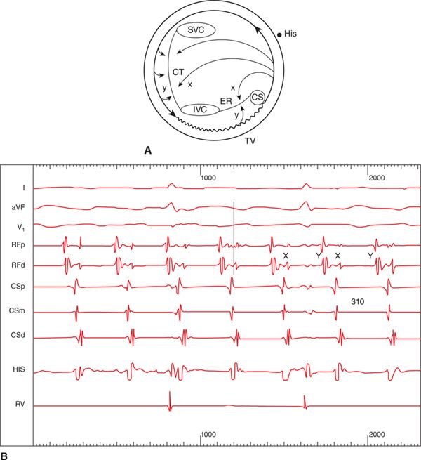
FIGURE 43-5 (A) Schematic diagram demonstrating where double potentials (x, y) are recorded during typical AFL along the Eustachian ridge and crista terminalis. (B) Double potentials recorded from an ablation catheter (RFp&d) positioned at the Eustachian ridge during typical AFL. Abbreviations: I, aVF, V1, surface ECG leads; RFp&d, proximal and distal bipolar recordings from the ablation catheter; CSp-d, proximal to distal CS electrogram recordings; RV, right ventricular electrogram recording. (Reproduced with permission from Feld GK, Srivatsa U, Hoppe B. Ablation of isthmus dependent atrial flutters. In: Huang SS, Wood MA, eds. Catheter Ablation of Cardiac Arrhythmias. Philadelphia: Elsevier; 2011.)
Slow conduction in the CTI may be caused by anisotropic fiber orientation, predisposing it to development of unidirectional block during rapid activation.2,8–10,15–19 The predominate clinical presentation of isthmus-dependent AFL is typical AFL, likely triggered by premature atrial contractions originating from the left atrium (LA) or nonsustained atrial fibrillation (AF),20 both of which result in clockwise unidirectional block in the CTI and initiation of counterclockwise macroreentry.
ECG PATTERNS OF TYPICAL (AND REVERSE TYPICAL) ATRIAL FLUTTER
In typical AFL, there is a characteristic inverted saw-tooth F wave pattern in the inferior leads II, III, and aVF. In reverse typical AFL, in contrast, the F wave pattern on the 12-lead ECG is less specific, often with a sine wave pattern in the inferior ECG leads (Figure 43-1A and B). The F wave pattern on ECG is dependent in part on the activation sequence of the LA, with inverted F waves in the inferior leads in typical AFL the result of activation of the left atrium initially near the coronary sinus (CS), and upright F waves in the inferior leads in reverse typical AFL resulting from activation of the LA near Bachman bundle.21,22 However, following LA ablation, and even right atrial ablation as in this case, the ECG presentation of isthmus-dependent AFL may be significantly different from the characteristic patterns described above.23
STANDARD CATHETER MAPPING OF ISTHMUS- DEPENDENT ATRIAL FLUTTER
Despite the characteristic 12-lead ECG pattern, electrophysiologic mapping and entrainment must be performed prior to radiofrequency catheter ablation of AFL. For standard catheter mapping, multielectrode catheters are typically positioned in the right atrium (RA), His bundle region, CS, and around the TVA (Figure 43-6). Recordings obtained during AFL (ie, spontaneous or induced) are then analyzed to determine the RA activation sequence. Typical or reverse typical AFL is confirmed by observing a counterclockwise or clockwise activation pattern in the RA around the TVA, respectively, (Figures 43-7A and B) and demonstration of concealed entrainment during pacing from the CTI (Figures 43-8 A and B).5
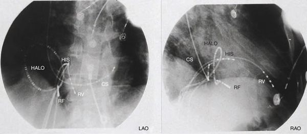
FIGURE 43-6 Left anterior oblique (LAO) and right anterior oblique (RAO) fluoroscopic projections showing common intracardiac positions of the right ventricular (RV), His bundle (HIS), coronary sinus (CS), Halo (HALO), and mapping/ablation catheters (RF). (Reproduced with permission from Feld GK, Srivatsa U, Hoppe B. Ablation of isthmus dependent atrial flutters. In: Huang SS, Wood MA, eds. Catheter Ablation of Cardiac Arrhythmias. Philadelphia: Elsevier; 2006:195-218.)
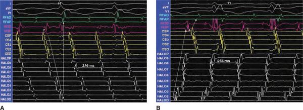
FIGURE 43-7 Endocardial electrograms from the mapping/ablation, Halo, CS, and His bundle catheters, and surface ECG leads I and aVF, during typical AFL (A) and reverse typical AFL (B). The atrial cycle length was 256 ms for both, and the arrows demonstrate the activation sequence. Abbreviations: CSP, electrograms recorded from the CS ostium; HISP, electrograms recorded at the proximal His bundle; RF, electrograms recorded from the mapping/ablation catheter in the CTI. (Reproduced with permission from Feld GK, Srivatsa U, Hoppe B. Ablation of isthmus dependent atrial flutters. In: Huang SS, Wood MA, editors. Catheter ablation of cardiac arrhythmias. Philadelphia: Elsevier; 2011.)
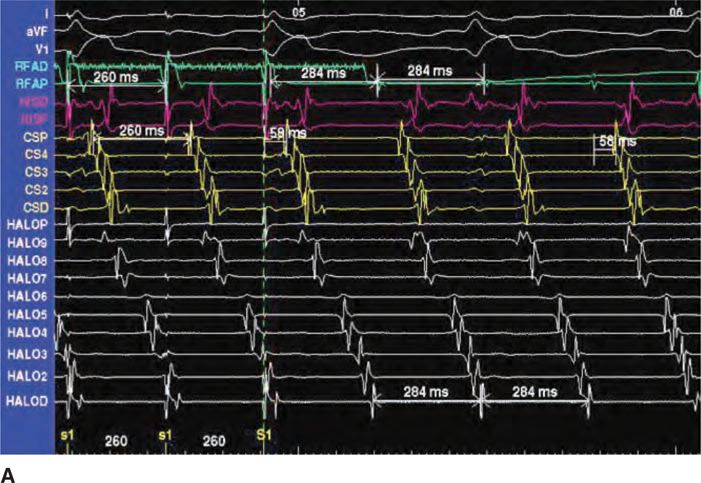
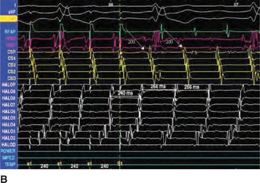
FIGURE 43-8 Endocardial electrograms from the RF, Halo, CS, and His bundle catheters, and surface ECG leads I, aVF, and V1, demonstrating concealed entrainment during pacing at the CTI in typical AFL (A) and reverse typical AFL (B). Abbreviations: Halo D-Halo P, bipolar electrograms from the distal to proximal poles of the Halo catheter around the TVA; CSP-D, bipolar electrograms recorded from the proximal to distal CS catheter electrode pairs; HISP&D, bipolar electrograms recorded from the proximal and distal His bundle catheter; RFAP&D, bipolar electrograms recorded from the proximal and distal electrode pairs of the mapping/ablation catheter at the CTI. (Reproduced with permission from Feld GK, Srivatsa U, Hoppe B. Ablation of isthmus dependent atrial flutters. In: Huang SS, Wood MA, editors. Catheter ablation of cardiac arrhythmias. Philadelphia: Elsevier; 2011.)
RADIOFREQUENCY CATHETER ABLATION OF TYPICAL ATRIAL FLUTTER
Radiofrequency catheter ablation (RFCA) of isthmus-dependent AFL is performed with a steerable mapping/ablation catheter positioned across the CTI via a femoral vein.3,5–7,24–26 Catheters with either saline-irrigated ablation electrodes (Thermocool Classic or SF, Biosense Webster, Inc, Diamond Bar, CA, or Chili, Boston Scientific, Inc., Natick, MA), or large distal ablation electrodes (ie, 8-10 mm Blazer, Boston Scientific, Inc, Natick, MA) are preferred for CTI ablation.27,29,30–33
The preferred target for isthmus-dependent AFL ablation is the CTI (Figure 43-9A).3,5–7,24–30,32,33 The ablation catheter is positioned across the CTI (Figure 43-6) with the ablation electrode near the TVA, midway between the septum and RA free wall, in order to record an atrial-to-ventricular electrogram amplitude ratio of 1:2 to 1:4 (Figure 43-6). The ablation catheter is then withdrawn a few millimeters at a time, pausing for 30 to 60 seconds at each location during a continuous or interrupted RF energy application. The catheter should be withdrawn until the ablation electrode records no atrial electrogram or until it is noted to abruptly slip off the Eustachian ridge. Radiofrequency energy application should be immediately interrupted when the catheter reaches the inferior vena cava, since ablation in venous structures may cause significant pain.
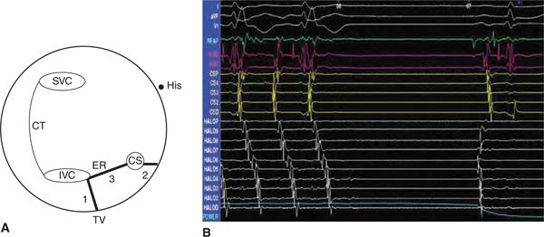
FIGURE 43-9 (A) A schematic diagram of the right atrium demonstrating the potential targets for ablation of CTI-dependent AFL. The preferred target for ablation is the CTI. (B) Surface ECG and endocardial electrogram recordings during ablation of the CTI showing termination of AFL. Abbreviations: I, aVF, V1, surface ECG leads; RFAP, proximal ablation electrogram; Hisp&d, proximal and distal His bundle electrograms; CSd-p, distal to proximal CS electrograms; Halo d-p, distal to proximal Halo catheter electrograms (Reproduced with permission from Feld GK, Srivatsa U, Hoppe B. Ablation of isthmus dependent atrial flutters. In: Huang SS, Wood MA, editors. Catheter ablation of cardiac arrhythmias. Philadelphia: Elsevier; 2011.)
PROCEDURE END POINTS FOR RADIOFREQUENCY CATHETER ABLATION OF TYPICAL ATRIAL FLUTTER
Ablation may be performed during AFL or sinus rhythm. If performed during AFL, the first end point is its termination (Figure 43-9B). After CTI ablation, electrophysiologic testing is required to ensure the presence of bidirectional conduction block (Figures 43-10A and B and 43-11A and B), which is confirmed by demonstrating a strictly cranial-to-caudal activation sequence in the contralateral RA, and widely spaced double potentials (ie, usually ≥120 ms apart) along the ablation line, during pacing from the low lateral right atrium and CS ostium, respectively (Figure 43-12).34–38 Electrophysiologic testing should be repeated up to 30 to 60 minutes after ablation to ensure that bidirectional CTI block persists, and that AFL cannot be reinduced, in order to significantly lower the risk of recurrent AFL during long-term follow-up.3,5–7,24–28,30–36,
Stay updated, free articles. Join our Telegram channel

Full access? Get Clinical Tree


