FIGURE 2-1. Schematic of single-beam (upper portion) and double-beam (lower portion) spectrophotometers. I = radiant light source; II = monochromator; III = analytical cuvette; IV = photomultiplier; V = recording device; VI = mirror.
Point-of-care testing may be thought of as any specimen testing that exists outside the walls of the large, central hospital laboratory. Community clinics, physician offices, emergency rooms, or patients’ homes are common examples. Currently, hand-held analyzers exist that are capable of accurately measuring many common analytes such as electrolytes, blood gases, pH, blood urea nitrogen (BUN), creatinine, lactate, glucose, lipids, coagulation factors, hemoglobin, and hematocrit.5 Wireless devices, such as PDAs, tablet PCs, and embedded computers are becoming commonplace at the patient’s bedside.
The principle technology that underlies the function of these smaller instruments usually involves biosensor systems. Biosensor systems consist of two components: a bioreceptor and a transducer. The bioreceptor is a molecule such as an antibody, enzyme, receptor protein, or nucleic acid that recognizes a target analyte. The interaction between the bioreceptor and the target analyte generates either a specific molecular species or results in a physiochemical change that can be measured by electrochemical methods. The transducer detects this change and converts it into a measurable signal that is proportional to the concentration of the analyte. Common transducers used in these systems are based on amperometry, such as measurement of hydrogen peroxide and oxygen; potentiometry, measurement of pH and ions; and photometry, which uses optical fibers. In contrast to conventional assay methods that involve multiple steps and liquid reagents, both components are integrated into one sensor in these portable instruments. In the future, the centralized laboratory will provide highly specialized testing and will be a source of information storage and retrieval, while point-of-care testing will likely continue to expand, providing clinicians with immediate results.6,7
Throughout the remainder of this text, many examples of the use of laboratory testing procedures are given as aids in diagnosing or confirming a diagnosis. These test procedures are based on one or more of the following methodologies.
PHOTOMETRY
Photometry is used to identify and/or quantify a given substance by measuring either the light absorbed or emitted on excitation by a specific narrow wavelength of light. In clinical laboratory instruments, the range of wavelengths measured is between 150 (the low ultraviolet) and 2500 nm (the near infrared region).8 These instruments are classified by the source of light as well as whether the light is absorbed or emitted. Four types of photometric instruments are currently in use in laboratories: molecular absorption, molecular emission (fluorometers), atomic emission (flame photometers), and atomic absorption spectrophotometers.
Molecular Absorption Spectrophotometers
Molecular absorption spectrophotometers, usually referred to as spectrophotometers, are commonly employed in conjunction with other methodologies, such as nephelometry and enzyme immunoassay (EIA). Spectrophotometers are easy to use, have relatively high specificity, and the results are highly accurate. The high specificity and accuracy are obtained by isolated analytes reacting with various substances that produce colorimetric reactions.
The basic components of two types of spectrophotometers (single and double beam) are depicted in Figure 2–1. Single-beam instruments have a light source (I) (e.g., a tungsten bulb or laser), which passes through an entrance slit that minimizes stray light. Specific wavelengths of light are selected by the use of a monochromator (II). Light of a specific wavelength then passes through the exit slit and illuminates the contents of the analytical cell (cuvette) (III). After passing through the test solution the light strikes a detector, usually a photomultiplier tube (IV). This tube amplifies the electronic signal, which is then sent to a recording device (V). The result is then compared with a standard curve to yield a specific concentration of analyte.
The double-beam instrument, similar in design to single-beam instruments, is designed to compensate for changes in absorbance of the reagent blank and light source intensity. It utilizes a mirror (VI) to split the light from a single source into two beams, one passing through the test solution and one through the reagent blank. By doing so, it automatically corrects optical errors as the wavelength changes.
Most measurements are made in the visible range of the spectrum, although sometimes measurements in the ultraviolet and infrared ranges are employed. The greatest sensitivity is achieved by selecting the wavelength of light in the range of maximum absorption. If substances are known to interfere at this wavelength, measurements may be made at a different wavelength in the absorption spectrum. This modified procedure allows detection or measurement of the analyte with minimal interference from other substances.
Molecular Emission Spectrophotometers
Molecular emission spectrophotometry is usually referred to as fluorometry. The technology found in these instruments is based on the principle of luminescence, that is, an energy exchange process that occurs when electrons absorb electromagnetic radiation and then emit this excited energy level at a lower level. Three types of fluorescence phenomena—fluorescence, phosphorescence, and chemiluminescence—form the principle on which these sensitive clinical laboratory instruments operate.
Fluorescence results from a three-stage process that occurs in certain molecules known as fluorophores. The first stage involves the absorption of radiant energy by an electron in the ground state creating an excited singlet state. During the very short lifetime of this state (order of nanoseconds), energy from the electronic-vibrational excited state is partially dissipated through a radiationless transfer of energy that results from interactions with the molecular environment and leads to the formation of a relaxed excited singlet state. This is followed by relaxation to the electronic ground state by the emission of radiation (fluorescence). Because energy is dissipated, the energy of the emitted photon is lower and the wavelength is longer than the absorption photon. The difference between these two energies is known as Stokes shift. This principle is the basis for the sensitivity of the different fluorescence techniques since the emission photons can be detected at a different wavelength band than the excitation photons. Consequently, the background is lower than with absorption spectrophotometry where the transmitted light is detected against a background of incident light at the same wavelength.9
The phenomenon of phosphorescence is similar to fluorescence since it also results from the absorption of radiant energy by a molecule. However, it is also a competitive process. Unlike fluorescence, which results from a singlet-singlet transition, phosphorescence is the result of a triplet-singlet transition. When a pair of electrons occupies a molecular orbital in the ground or excited state, a singlet state is created. In this state, the electrons must have opposite spins (the Pauli exclusion principle), and only one magnetic moment is derived from this state. When the electrons are no longer paired, three different arrangements are possible, each with a different magnetic moment, the triplet state. The electronic energy of a triplet state is lower than a singlet state. Therefore, when the relaxed excited singlet state overlaps with a higher triplet state, energy may be transferred through a process called intersystem crossing. As in the case of an excited singlet state, energy may be dissipated through several radiationless mechanisms to the electronic ground state. However, when a triplet-singlet transition occurs, the result is phosphorescence. The probability of this type of transition is much lower than a singlet-singlet transition (fluorescence), and the emission wavelength and decay times are also longer than for fluorescence emission. Because the various forms of radiationless energy transfer compete so effectively, phosphorescence is generally limited to certain molecules, such as many aromatic and organometallic compounds, at very low temperatures, or in highly viscous solutions.9,10
The phenomenon of chemiluminescence is also similar to that of fluorescence in that it results from light emitted from an excited singlet state. However, unlike both fluorescence and phosphorescence, the excitation energy is caused by a chemical or electrochemical reaction. The energy is typically derived from the oxidation of an organic compound, such as luminol, luciferin, and acridinium ester. Light is derived from the excited products that are formed in the reaction.
Different instruments have been developed that use these basic principles of luminescence. These devices use similar basic components along the following pathway: a light source (laser or mercury arc lamp), an excitation monochromator, a sample cuvette, an emission monochromator, and a photodetector.8 While the principles of these instruments are relatively straightforward, various modifications have been developed for specific applications.
An important example is fluorescent polarization in fluorometers. Fluorescent molecules (fluorophores) become excited by polarized light when the plane of polarization is parallel to their absorption transition vector, provided the molecule remains relatively stationary throughout the excited state. If the molecules rotate rapidly, light will be emitted in a different plane than the excitation plane. The intensity of light emitted by the molecules in the excitation polarization plane and at 90° permits the fluorescence polarization to be measured. The degree to which the emission intensity varies between the two planes of polarization is a function of the mobility of the fluorophore. Large molecules move slowly during the excited state and will remain highly polarized. Small molecules that rotate faster will emit light that is depolarized relative to the excitation plane.10
One of the most common applications of fluorescence polarization is competitive immunoassays, used to measure a wide range of analytes including therapeutic and illicit drugs, hormones, and enzymes. This important methodology involves the addition of a known quantity of fluorescent-labeled analyte molecules to a serum antibody (specific to the analyte) mixture. The labeled analyte will emit depolarized light because its motion is not constrained. However, when it binds to an antibody, its motion will decrease and the emitted light will be more polarized. When an unknown quantity of an unlabeled analyte is added to the mixture, competitive binding for the antibody will occur and reduce the polarization of the labeled analyte. By using standard curves of known drug concentrations versus polarization, the concentration of the unlabeled analyte can be determined.10
Another important application of fluorometry is flow cytometry, discussed later in this chapter. Like many modern laboratory instruments, flow cytometry involves the application of multiple physical, chemical, and biological principles and is, therefore, best considered as a separate category.
Atomic Emission and Atomic Absorption Spectrophotometers
Atomic emission (flame photometry) and atomic absorption spectrophotometry have limited use in modern laboratories. In the past, concentrations of metallic elements such as sodium, potassium, and lithium were commonly determined by flame photometry. The technique is based on the elementary quantum principle that electrons in an atom are excited to a higher energy level by heat. The electrons, being unstable in this state, return to a lower energy state. In doing so, the excess energy is liberated as photons in the visible light range. Usually, multiple energy levels are involved and the resulting spectral patterns are characteristic of each element. When conditions are held constant, the concentration of each ion is proportional to the light intensity at its characteristic wavelength.
Atomic absorption spectrophotometry procedures are currently associated mainly with toxicology laboratories where poisonous substances, such as lead and arsenic, need to be identified. Unlike flame photometry, the element that is analyzed by this technique is not appreciably excited. Rather, the element is dissociated from its chemical bonds. In this state, the element is in its lowest energy state and capable of absorbing energy in a narrow range that corresponds to its line spectrum.11 Atomic absorption spectrophotometers are much more sensitive than flame photometers and more specific since the light sources used (hollow cathode lamps) emit at wavelengths that are specific for the element being measured.2
TURBIDIMETRY AND NEPHELOMETRY
When light passes through a solution, it can be either absorbed or scattered. Turbidimetry is the technique for measuring the percent light absorbed. A major advantage of turbidimetry is that measurements can be made with laboratory instruments, such as a spectrophotometer, used for other procedures in laboratory testing. Errors associated with this method usually involve sample and reagent preparation. For example, since the amount of light blocked depends on both the concentration and size of each particle, differences in particle size between the sample and the standard is one cause of error. The length of time between sample preparation and measurement, another cause of error, should be consistent since particles settle to varying degrees, allowing more or less light to pass. Large concentrations are necessary because this test measures small differences in large numbers.
Nephelometry, similar to turbidimetry, is the technique used for measuring the scatter of light by particles. The main differences are that (1) the light source is usually a laser, and (2) the detector, used to measure scattered light, is at a right angle to the incident light. Beam light scattered by particles is a function of the size and number of the particles. Nephelometric measurements are more precise than turbidimetric ones since the smaller signal generated for low analyte concentrations is more easily detected against a very low background.12 Because antigen–antibody complexes are easily detected by this method, it is commonly employed in combination with EIAs.
REFRACTOMETRY
Refractometry measurements are based on the principle that light bends as it passes through different media. The ability of a liquid to bend light depends on several factors: wavelength of the incident light, temperature, physical characteristics of the medium, and the solute concentration in the medium. By keeping the first three parameters constant, refractometers can measure the total solute concentration of a liquid. This procedure is particularly useful, especially as a rapid screening test, since no chemical reagents and reactions are involved.8
Refractometers are commonly used to measure total dissolved plasma solids (mostly proteins) and urine specific gravity. In the refractometer, light is passed through the sample and then through a series of prisms. The refracted light is projected on an eyepiece scale. The scale is calibrated in grams per deciliter for serum protein, and in the case of urine, for specific gravity. In the eyepiece, a sharp line of demarcation is apparent and represents the boundary between the sample and distilled water. In the case of plasma samples, the refraction angle is proportional to the total dissolved solids. Although proteins are the predominant chemical species, other substances such as electrolytes, glucose, lipids, and urea contribute to the refraction angle. Therefore, measurements made on plasma do not correlate exactly to the true protein concentrations, but as the nonprotein solutes contribute to the total solutes in a predictable manner, accurate corrections are possible.13
OSMOMETRY
In the clinical laboratory, osmometer readings are interpreted as a measure of total concentration of solute particles and are used to measure the osmolality of biological fluids such as serum, plasma, and urine. When osmotically active particles are dissolved in a solvent (water, in the case of biological fluids), four physical properties of the water are affected: the osmotic pressure and the boiling point are increased, and the vapor pressure and the freezing point are decreased. Since each property is related, they can be expressed mathematically in terms of the others (colligative properties) and to osmolality. Consequently, several methods can be used to measure osmolality including freezing-point depression, colloid osmotic pressure (COP), and vapor pressure osmometry.14
The most commonly used devices to measure osmolality or other colligative properties of a solution are freezing-point depression osmometers. These are simple devices consisting of a sample chamber with a stirrer and a thermistor, a cooling chamber containing antifreeze, and a potentiometer with a direct readout. The sample is rapidly cooled several degrees below its freezing point in the cooling chamber. The sample is stirred to initiate freezing of the super-cooled solution. When the freezing point of the solution is reached (the point where the rate of the heat of fusion released by ice formation comes into equilibrium with the rate of heat removal by the cooling chamber), the osmolality can be calculated.8
In certain situations, it is important to measure the COP, a direct measure of the contribution of plasma proteins to the osmolality. Because of the large molecular weight of plasma proteins, their contribution to the total osmolality is very small as measured by freezing-point depression and vapor pressure osmometers. Since a low COP favors a shift of fluid from the intravascular compartment to the interstitial compartment, measurement of the COP is particularly important in monitoring intravascular volume and useful in guiding fluid therapy in different circumstances to prevent peripheral and pulmonary edema.
ANA = antinuclear antibody; BUN = blood urea nitrogen; ELISA = enzyme-linked immunosorbent assay; EMIT = enzyme-multiplied immunoassay technique; FPIA = fluorescent polarization immunoassay; GC = gas chromatography; HPLC = high-performance liquid chromatography; ISEs = ion-selective electrodes; PCR = polymerase chain reaction; TCAs = tricyclic antidepressants.
The COP osmometer, also known as a membrane osmometer, consists of two fluid-filled chambers separated by a semipermeable membrane. One chamber is filled with a colloid-free physiologic saline solution that is in contact with a pressure transducer. When the plasma or serum is placed in the sample chamber, fluid moves by osmosis from the saline chamber to the sample chamber, thus causing a negative pressure to develop in the saline chamber. The resultant pressure is the colloidal osmotic pressure.14
ELECTROCHEMISTRY
In the clinical laboratory, analytic electrochemical techniques involve the measurement of current or voltage produced by the activity of different types of ions. These analytic techniques are based on the fundamental electrochemical phenomena of potentiometry, coulometry, voltammetry, and conductometry.
Potentiometry
Potentiometry involves the measurement of electrical potential differences between two electrodes in an electrochemical cell at zero current flow. This electrochemical method is based on the Nernst equation, which relates the potential to the concentration of an ion in solution, to measure analyte concentrations.15 Each electrode or half-cell in an electrochemical cell consists of a metal conductor that is in contact with an electrolyte solution. One of the electrodes is a reference electrode with a constant electric potential; the other is the measuring or indicator electrode. The boundaries between the ion conductive phases in the cell determine the type of potential gradients that exist between the electrodes and are defined as redox (oxidation reduction), membrane, and diffusion potentials.
A redox potential occurs when the two electrolyte solutions in the electrochemical cell are brought into contact with each other by a salt bridge so that the two solutions can achieve equilibrium. A potentiometer may be used to measure the potential difference between the two electrodes. This is known as the redox potential difference since the reaction involves the transfer of electrons between substances that accept electrons (oxidant) and substances that donate electrons (reductant). Junctional potentials rather than redox potentials occur when either a solid state or liquid interface exists between the ion conductive phases. These produce membrane or diffusion potentials, respectively. In each case the concentration of an ion in solution can be measured using the Nernst equation, which relates the electrode potential to the activity of the measured ions in the test solution8:
E = E0 – (0.059/z)log (Cred/Cox)
where E = the total potential (in mV), E0 = is the standard reduction potential, z = the number of electrons involved in the reduction reaction, Cred = the molar concentration of the ion in the oxidized form, and Cox = the molar concentration of the ion in the reduced form.
Ion-selective electrodes (ISEs) consisting of a membrane that separates the reference and test electrolyte solutions are very selective and sensitive for the ions that they measure. For this reason further discussion on potentiometry will focus on these types of electrodes.
The ISE method, having comparable or better sensitivity than flame photometry, has become the principal test for determining urine and serum electrolytes in the clinical laboratory. Typically, ion concentrations such as sodium, potassium, chloride, calcium, and lithium, are measured using this method (Table 2-1).
The principle of ISE involves the generation of a small electrical current when a particular ion comes in contact with an electrode. The electrode selectively binds the ion to be measured. To measure the concentration, the circuit must be completed with a reference electrode. The three types of electrodes are
- Ion-selective glass membranes
- Solid-state electrodes
- Liquid ion-exchange membranes
As shown in Figure 2-2, ion-selective glass membranes preferentially allow hydrogen (H+), sodium (Na+), and ammonium (NH4+) ions to cross a hydrated outer layer of glass. The H+ glass electrode or pH electrode is the most common electrode for measuring H+. Electrodes for Na+, potassium (K+), lithium (Li+), and NH4+ are also available. An electrical potential is created when these ions diffuse across the membrane.
Solid-state electrodes consist of halide-containing crystals for measuring specific ions. An example is the silver–silver chloride electrode for measuring chloride.8 Liquid ion-exchange membranes contain a water-insoluble, inert solvent that can dissolve an ion-selective carrier. Ions outside the membrane produce a concentration-related potential with the ions bound to the carrier inside the membrane.8
The electrodes are separated from the sample by a liquid junction or salt bridge. Since the liquid junction generates its own voltage at the sample interface, it is a source of error. This error is overcome by adjusting the composition of the liquid junction.16 Another source of error is the selectivity of the electrode. Therefore, careful electrode selection is important. Overall, this method is simple to use and more accurate than flame photometry for samples having low plasma water due to conditions such as hyperlipoproteinemia.17
Ion-selective electrodes are relatively inexpensive and simple to use compared to other techniques and have an extremely wide range of applications and wide concentration range. They are also very useful in biomedical applications because they can measure the activity of the ion directly in addition to the concentration.
Coulometry
Coulometry is an analytical method for measuring an unknown concentration of an analyte in solution by completely converting the analyte from one oxidation state to another. This is accomplished through a form of titration where a standardized concentration of the titrant is reacted with the unknown analyte, requiring no chemical standards or calibration. The point at which all of the analyte has been converted to the new oxidation state is called the endpoint and is determined by some type of indicator that is also present in the solution.
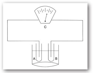
FIGURE 2-2. The pH meter is an example of a test that uses ISE to measure the concentration of hydrogen ions. An electric current is generated when hydrogen ions come in contact with the ISE (A). The circuit is completed through the use of a reference electrode (B) submerged in the same liquid as the ISE (also known as the liquid junction). The concentration can then be read on a potentiometer (C).
This technique is based on the Faraday law, which relates the quantity of electric charge generated by an amount of substance produced or consumed in the redox process and is expressed as
znF = It = Q
where z is the number of electrons involved in the reaction, n is the quantity of the analyte, F is the Faraday constant (96,487 C/mol), I is the current, t is time, and Q is the amount of charge that passes through the cell.
The chloridometer is a common instrument that employs this method. This instrument may be used to measure the chloride ion (Cl–) concentration in sweat, urine, and CSF samples.8 The device uses a constant current across two silver electrodes. The silver ions (Ag+) that are generated at a constant rate react with the Cl– ions in the sample. The reaction that produces insoluble AgCl ceases once excess Ag+ ions are detected by an indicator and reference electrodes. Since the quantity of Ag+ ions generated is known, the quantity of Cl– ions may be calculated using the Faraday law.
Voltammetry
Voltammetry encompasses a group of electrochemical techniques in which a potential is applied to an electrochemical cell with the simultaneous measurement of the resulting current. By varying the potential of an electrode, it is possible to oxidize and reduce analytes in a solution. At more positive potentials, the electrons within the electrode become lower in energy and the oxidation of species in a solution becomes more likely. At lower potentials, the opposite occurs. By monitoring the current of an electrochemical cell at varying electrode potentials, it is possible to determine several parameters such as concentration, reaction kinetics, and thermodynamics of the analytes.14
This technique differs from potentiometry in a number of important ways. Voltammetric techniques use an externally applied force (potential) to generate a signal (current) in a way that would not normally occur, whereas in potentiometric techniques the analytical signal is produced internally through a redox reaction. The electrode arrangement is also quite different between the two techniques. In order to analyze both the potential and the resulting current, three electrodes are employed in voltammetric devices. The three electrodes include the working, auxiliary, and reference electrodes, which (when connected through a voltmeter) permit the application of specific potential functions. The measurement of the resulting current can yield results about ionic concentrations, conductivity, and diffusion. The ability to apply different types of potential functions or waveforms has led to the development of different voltammetric techniques: linear potential sweep polarography, pulse polarography, cyclic voltammetry, and anode stripping voltammetry.8 These analytical methods, though not commonly used in clinical laboratories, are very sensitive (detection limits as low as the parts per billion range) and are capable of identifying trace elements in patient tissues such as hair and skin.
Conductometry
Conductometry is the measurement of current flow (proportional to conductivity) between two nonpolarized electrodes of which a known potential has been established. Clinical applications include urea estimation through the measurement of the rate-of-change of conductance that occurs with the urease-catalyzed formation of NH4+ and bicarbonate (HCO3–). The technique is limited at low concentrations because of the high conductance of biological fluids. Perhaps the most important application of impedance (inversely proportional to conductance) measurements in the clinical laboratory involves the Coulter principle for the electronic counting of blood cells. This method is discussed in detail in the cytometry section.
ELECTROPHORESIS
Routine diagnostic applications of electrophoresis technology exist for infectious diseases, malignancies, genetic diseases, paternity testing, forensic analysis, and tissue typing for transplantation. Electrophoresis tests, an important clinical laboratory method for molecular separations, involve the movement of charged molecules in a solution or on a support medium, associated with a direct current electrical field. The movement of molecules in this electrical field is dependent on molecular charge, shape, and size.18 Since most molecules of biologic importance are both water-soluble and charged, this analytical tool is one of the most important techniques for molecular separation in the clinical laboratory. The main types of electrophoresis techniques used in both clinical and research laboratories include cellulose acetate, agarose gel, polyacrylamide gel, isoelectric focusing, two-dimensional, and capillary electrophoresis (CE). Because of a large number of clinical applications, electrophoresis apparatus, cellulose acetate and agarose gels, and reagents are available from commercial suppliers for each of these specific applications.
The primary application of electrophoresis is the analysis and purification of very large molecules such as proteins and nucleic acids. Electrophoresis also can be applied to the separation of smaller molecules, including charged sugars, amino acids, peptides, nucleotides, and simple ions. Through the proper selection of the medium for electrophoretic separations, extremely high resolution and sensitivity of separation can be achieved. Electrophoretic systems are usually combined with highly sensitive detection methods to monitor and analyze the separations that suit the specific application.19
The basic electrophoresis apparatus consists of a high voltage direct current supply, electrodes, a buffer, and a support for the buffer or a capillary tube. Supports for the buffer include filter paper, cellulose acetate membranes, agarose, and polyacrylamide gels. When an electrostatic force (EOF) is applied across the electrophoresis apparatus, the charged molecules will migrate to the anode or the cathode of the system depending on their charge. The force that acts on these molecules is proportional to the net charge on the molecular species and the applied voltage (electromotive force). This relationship is expressed as
F = qE/d
where F is the force exerted on the charged molecule, q is its net charge, E is the electromotive force, and d is the distance across the electrophoretic medium.14
While the basic principles are simple, procedures employed in the electrophoresis process are considerably more complex. Molecules to be separated must be dissolved in a buffer that contains electrolytes, which carry the applied current and fix the pH. The mobility of the molecules will be affected locally by the charge of the electrolytes, the viscosity of the medium, their size, and degree of asymmetry. These factors are related by the following equation:
µ = q/6ηr
where µ is the electrophoretic mobility of the charged molecule, q is its net charge, η is the viscosity of the medium, and r is the ionic radius.20
The conditions in which this process occurs are further complicated by the use of a support medium, necessary to minimize diffusion and convective mixing of the bands (caused by the heated current flowing through the buffer). Media used include polysaccharides (cellulose and agarose) and synthetic media such as polyacrylamide. The porosity of these media will, to a large extent, determine the resistance to movement for different ionic species. Therefore, the type of support medium used depends on the application. The above cited factors affecting the process of electrophoresis are controllable and provide optimal resolution for each specific application.
Cellulose Acetate and Agarose Gel Electrophoresis
Cellulose acetate and agarose gel electrophoresis are commonly used for both serum protein and hemoglobin separations. Serum protein electrophoresis is often used as a screening procedure for the detection of disease states, such as inflammation, protein loss, monoclonal gammopathies, and other dysproteinemias. When the molecules have been separated into bands, specific stains are used to visualize them. Densitometry is typically used to quantify each band. When a monoclonal immunoglobulin pattern is identified, another technique, immunofixation electrophoresis, is used to quantify the immunoglobulins IgG, IgA, IgM, IgD, and IgE. Once these proteins are separated on an agarose gel, specific antibodies directed at the immunoglobulins are added. The sample is then fixed and stained to visualize and quantify the bands.21 Separation of proteins may also be accomplished with isoelectric focusing where the proteins migrate through a stable pH gradient with the pH varying in the direction of migration. Each protein moves to its isoelectric point (i.e., the point where the protein’s charge becomes zero and migration ceases). This technique is often used for separation of isoenzymes and hemoglobin variants.
Stay updated, free articles. Join our Telegram channel

Full access? Get Clinical Tree


