(1)
BIOTEC, Biophysics, Technische Universität Dresden, Dresden, Germany
(2)
Cellular and Molecular Biophysics, Max Planck Institute of Biochemistry, Martinsried, Germany
Abstract
Fluorescence correlation spectroscopy (FCS) can add dynamic molecular information to images of live cells. For example, a confocal laser scanning microscope (CLSM) equipped with an accessory FCS unit provides the possibility to first image the spatial distribution of a fluorescent protein before probing its mobility within defined regions of interest. Whereas specific protein–protein interactions are preferably assayed with a dual-color approach, single-color FCS can still provide valuable information about the size of the diffusing entities and potential interactions with other, nonfluorescent, proteins or subcellular structures. Because number fluctuations are measured, the concentrations of freely diffusing complexes and their state of oligomerization are accessible.
Key words
Fluorescence correlation spectroscopyGreen fluorescent proteinHeterologous expressionConfocal laser scanning microscopyDiffusion coefficientObstructed diffusionProtein–protein interactionsMolecular brightnessIntracellular concentrations1 Introduction
With FCS the diffusion properties and concentrations of fluorescent particles are measured in free solution by recording and correlating a fluorescence signal originating from an illuminated tiny, subfemtoliter-sized spot. The microscopic observation volume is usually implemented by a confocal optical alignment, for example, as provided by a CLSM. FCS is measurable in solutions from higher pico- to lower micromolar concentrations (~100 pM to 1 μM). For too high concentrations, the relative fluctuations are too small to be measurable. For too low concentrations, very long measurement times are needed to collect a sufficient number of molecular events. As a rule of thumb, 1 nanomolar (1 nM) solution is well suited for measuring FCS in free solution as well as in living cells with recordings in the time scale of several minutes (1 nM × 1 f × N A ≈ 1 particle in the observation volume). The output of a single-color FCS measurement is the time-correlated fluorescence signal displayed as an autocorrelation curve (ACF, e.g., see Figs. 2–5). Pairs of parameters for both correlation times of the decay (on the abscissa) and corresponding contributions to the fluctuation amplitude (on the ordinate) are extracted by fitting appropriate model functions to the ACF. Fitting provides a set of times constants which have to be assigned to underlying physical processes like fluorophore blinking and the different mobility states of the particles.
An overview about FCS theory, application, and instrumentation can be found in numerous papers [1–7]. The autocorrelation function (ACF; G(τ)) is generated from the fluorescence signal F(t)
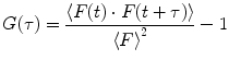
and evaluated by the experimenter with a set of assumptions. For example, a widely used model function for 3D-diffusion with triplet-blinking is of the form [8]
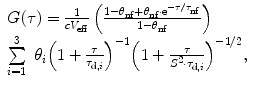
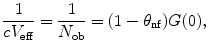
assuming a three-dimensional (3D) Gaussian shape of the observation volume 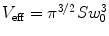 and a single nonfluorescent state (see Note 1). In this model, the observation volume is assumed to be stretched along the optical axis z by a factor S = z 0/w 0. The beam waist w 0 denotes the radius along which the intensity profile decays from the center to 1/e 2. The time constant for populating nonfluorescent states τ nf and up to 3 diffusion times τ d,i as well as their fractional contributions to the fluctuation amplitude, θ nf and θ i , can be extracted as parameters. If the fluorescent ensemble is homogeneous in molecular brightness, the inverse, dark state-corrected intercept of the ACF equals the average number of fluorescent molecules in the detection volume V eff
(1)
(2)
and a single nonfluorescent state (see Note 1). In this model, the observation volume is assumed to be stretched along the optical axis z by a factor S = z 0/w 0. The beam waist w 0 denotes the radius along which the intensity profile decays from the center to 1/e 2. The time constant for populating nonfluorescent states τ nf and up to 3 diffusion times τ d,i as well as their fractional contributions to the fluctuation amplitude, θ nf and θ i , can be extracted as parameters. If the fluorescent ensemble is homogeneous in molecular brightness, the inverse, dark state-corrected intercept of the ACF equals the average number of fluorescent molecules in the detection volume V eff(3)
In the following, I describe a tutorial of how to perform a single-point, single-color FCS experiment with continuous wave laser excitation inside living cells. The goal is to illustrate how a cytoplasmic protein fused to enhanced green fluorescent protein (EGFP) can be characterized under native conditions. The approach comprises cloning of the EGFP-fusion construct, characterization of the microscope with an organic dye (Alexa488), and probing of the EGFP sensor with increasing environmental complexity. A vector system is introduced for expression of the fluorescent protein in concentrations suitable for FCS. Finally, application of the method is illustrated with data obtained for EGFP-tagged human Janus kinase 3 (JAK3) in the cytoplasm of an epithelial cancer cell line.
2 Materials
1.
Mammalian expression vector (pEGFP-N1, Clontech).
2.
Inducible mammalian vector expression system (Complete Control; Stratagene).
3.
Inducible human adherent cell line (ER293; Stratagene).
4.
Culture media (Dulbecco’s Modified Eagle Medium (DMEM) with 10 % FCS; Gibco).
5.
Transfection reagent (Attractene; Quiagen).
6.
Air buffer (150 mM NaCl, 20 mM Hepes pH 7.4, 15 mM Glucose, 46 mM Trehalose, 5.4 mM KCl, 0.85 mM MgSO4, 1.7 mM CaCl2, 0.15 mg/ml BSA).
7.
Human fibronectin (lyophilized, Roche).
8.
Chambered cover glass #1 (8-well Cat. No.:#155411, Nunc).
9.
Nuclear stain (DRAQ5, Biostatus Limited, UK).
10.
AlexaFluor 488-TFP (CatNo.:#30005, Invitrogen/Molecular Probes, USA).
11.
Recombinant EGFP (CatNo.:#4999-100, BioVision, USA).
12.
Confocal microscope equipped with FCS unit (e.g., Confocor3, Zeiss, Germany).
3 Methods
The protocol includes (1) the preparation of the samples and cells, (2) adjustment of the microscope, (3) the required control measurements, and (4) intracellular measurements and interpretation of the data.
3.1 Expression of Fluorescent Protein in Culture Cells
Heterologous expression of EGFP-tagged fusion constructs is now standard in cell biology. However, many vector systems contain powerful viral promoters and produce much higher expression levels as they are needed for FCS. For example, cytomegalovirus (CMV)-driven transcription of EGFP with the widely used vector pEGFP-N1 (Clontech) will accumulate μM concentration of fluorescent protein inside the cells. In addition, due to stochastic incorporation of plasmids, the individual cellular expression levels vary over three orders of magnitude and thus charge the experimenter with extra time to search and select suitable cells for FCS analysis. Therefore, it is convenient to lower expression by using either very weak promoters or inducible expression systems (see Note 2).
3.1.1 Cloning
DNA manipulation was performed by standard recombinant DNA methods. The vector pEGSH-EGFP was generated by subcloning the coding sequence of EGFP from pEGFPP-N1 (Clontech) into pEGSH (Stratagene) via BamH1/NotI restriction sites (Fig. 1a). JAK3 was inserted into pEGFP-N1 via XhoI/SacII as described [9]. pJAK3-EGFP was kindly donated by Sigrun Hofmann (Fig. 1b).
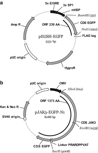
Fig. 1
Vector maps. (a) Schematic drawing of pEGSH-EGFP expression plasmid for cytoplasmic EGFP. (b) Schematic drawing of expression plasmid pJAK3-EGFP-N1 for the expression of C terminally EGFP-tagged JAK3
3.1.2 Transient Transfection of ER293 Culture Cells
ER293 cells were passaged in DMEM supplemented with 10 % fetal bovine serum and 300 μg/ml G418. Subconfluent cells were harvested by trypsination and diluted to 8 × 10⁴ cells/ml. The chambered 8-well cover slips were coated by covering the glass surface with 10 μg/ml human fibronectin in PBS followed by incubation of 30 min at 37 °C. Fibronectin was aspirated and 200 μl cell suspension seeded immediately into the well. After 24 h, the medium was replaced prior to adding 50 μl of transfection mix (100 ng DNA and 0.38 μl Attractene in OptiMEM). Three hours after transfection, the supernatant was replaced with fresh medium. The cells can be observed after 12–24 h for up to 2 days, depending on confluence.
3.1.3 Prepare for Imaging
From a biological perspective, observing cells under physiological conditions at 37 °C and CO2 containing, humidified atmosphere may seem ideal; however, there are drawbacks for FCS analysis. Cell motility is much faster; therefore, the internal membrane systems are in constant motion. Under such conditions, it is difficult to find homogeneous regions within the cytoplasm which are not constantly crossed by mitochondria and other organelles. Organelles may exclude the fluorescent protein. Dark (or bright) organelles which transverse the detection volume lead to dramatic intensity changes which render the correlation data worthless.
The measurements described here have been performed at room temperature (22 °C). Cells were mounted on cover slides on top of a microscope stage. In principle one could measure in culture media. However, because FCS is performed at rather low concentrations, the background fluorescence from the medium is significant. In addition, when removing the cells from the incubator, the CO2 release leads to a rapid increase of pH, which may induce unwanted physiological stress. Therefore, cells were observed in a sterile translucent air buffer (for the composition, see Subheading 2) [10]. The solution contained a Hepes-based pH buffering system, physiological salts, and trehalose to alleviate osmotic stress. Measurements in air buffer can be performed for several hours.
Although the intracellular EGFP distribution provides some contrast, for proper positioning inside the cell, it may be beneficial to stain the nucleus. Here, I used DRAQ5, a 633 nm excitable intercalating dye in the far red, which does not interfere with the EGFP emission window. For staining, a 5 mM stock was freshly diluted 1:1,000 in air buffer, incubated 5–10 min at RT, and washed once in air buffer.
3.2 The Microscopic Settings
Although the microscope systems for measuring FSC may feature some differences, there is a common set of parameters which has to be checked by the user.
3.2.1 Confocal Alignment
By using a solution of organic dye as a fluorescent standard, like Alexa488, the system has to be optimized for a good confocal alignment. While positioning the focus in the solution, confocality is improved by iteratively moving the pinhole and the aperture of the photon counting detector to maximum signal position. With a ConfoCor3, this has been automated, and the user just activates a software routine. When the alignment is far off, it is useful to start with higher, e.g., μM concentrations of dye. At maximum signal, the correction collar of the objective has to be adjusted for maximum counts per particle (CPP) or, if the product of the intercept of the ACF and the mean intensity is not monitored by the control software, the amplitude of the ACF (see Note 3). For the ConfoCor3 microscope, it was sufficient to optimize simply the count rate since the maxima for intensity and amplitude did coincide; however, this may not always be the case. As a result, one should be able to record correlation data with at least 10 kHz counts per particle.
Generally, the quality of the alignment is validated by fitting a 1-component model function (Eq. 2 for i = 1) to the measured ACF for Alexa488 and to check, whether the residuals omit a systematic deviation (example ACF, see Fig. 2c, d). If the residuals are biased, the alignment should be improved because the point spread function may deviate from a 3D Gaussian distribution.
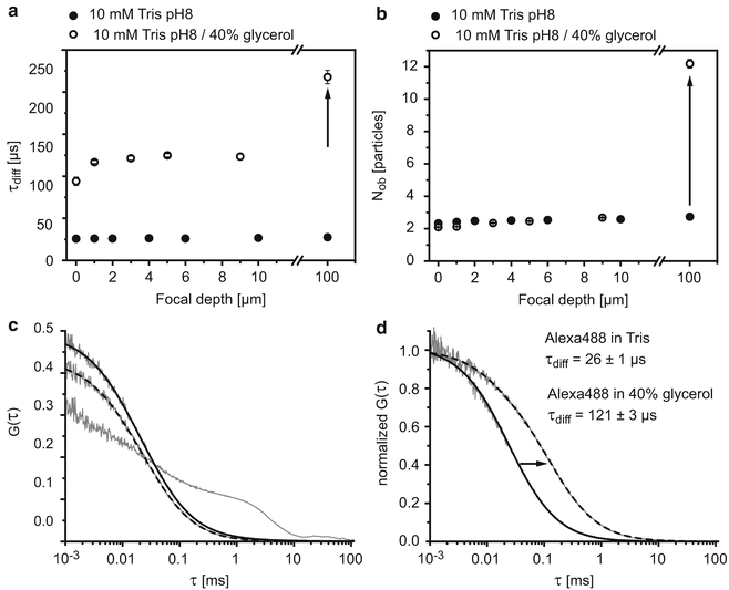
Fig. 2
Control measurements using an organic dye. Diffusion times (a) and particle numbers N ob (b) of Alexa488 in Tris buffer containing 0 % (closed circles) or 40 % glycerol (open circles). (c) ACFs at different distances from the glass surface z = −1 μm, z = 1 μm (dashed fit), and z = 10 μm (straight fit). (d) Normalized ACF for EGFP in PBS (straight fit) and 40 % glycerol (dashed fit)
3.2.2 Pinhole
The optimal pinhole size is determined by the maximum counts per particle detectable for a given excitation intensity. Diameters between 50 and 90 μm are commonly used. With a simple home-made confocal optical setup using a pinhole between 50 and 70 μm in combination with a Olympus 63× 1.2 W objective, dwell times for Alexa488 between 35 and 50 μs can be measured [11, 12]. With a ConfoCor3, the beam additionally passes a system of projecting lenses between the pinhole and the back aperture of the objective resulting in dwell times of 25 μs, even when using a 90 μm pinhole in combination with a lower magnification objective Zeiss 40× 1.2 W (Fig. 1a, d).
3.2.3 Laser
Diffusion times can be measured provided the average signal remains constant within the measurement time of several minutes. However, if the counts per particle are compared between different sets of measurements, one has to assure long-term stability of the laser. Since an Argon ion laser may require pre-warming of several hours, a laser intensity monitor is suitable to recalibrate the values. However, the absolute laser power is usually not accessible during the experiment. Recording 10 kHz per particle from a nanomolar solution of Alexa488 in water corresponds to an excitation intensity of about 2 kW/cm2 as measured with a 40× 1.2 W objective [13]. Thus, for FCS measurements in a diffraction-limited confocal spot (w 0 ≅ 200 nm), several μW are sufficient for excitation.
3.3 Measuring FCS
The following section lists the individual steps of how to perform a FCS measurement and, more importantly, shows with examples how the user can interpret the measured parameters.
Stay updated, free articles. Join our Telegram channel

Full access? Get Clinical Tree


